EnigmaMuseum.com
is devoted to locating, restoring, displaying, demonstrating, researching and trading in Enigma cipher machines and related equipment. We maintain an on-line museum and offer a detailed book and CD-ROM Enigma Library. With our extensive network of historians, collectors and skilled restoration specialists, we provide Cipher machines, information and services as listed below.
------------------------------------------
SCROLL Down Page or SELECT from this WEBSITE INDEX:

* ENIGMAS & other Cipher Machines FOR SALE:
As cipher machines have taken on increasingly important roles in world history, considerable interest has developed in collecting and studying these early technological innovations.
For over 20 years we have been actively searching for examples of the Enigma cipher machines that the Germans relied on to keep their military communications secret during WW-2. Very few Enigmas survived the war and since the Allies were commanded to destroy every one that they found, it is a real challenge to find them. Each Enigma has a story to tell and careful research and disassembly can provide clues to its hisory.
We work with a group of dedicated historians, collectors and technicians to uncover Enigma history and we make it available through EnigmaMuseum.com. A Virtual Museum like this is the ideal format for making these rare and interesting historic instruments available to view and study.
We have put the information in our book and CD-ROM Enigma Library. We give lectures and demonstrations and provide Enigmas as displays for museums and props for media and occasionally sell an Enigma to help defray our expenses. More recently, we have found other historic cipher machines including a fascinating Russian Cold War era Fialka cipher machine.
We attempt to display as much of this information as possible in our frequently-updated museum pages and we welcome comments and questions.
The German Enigma Cipher Machine played a critical role in the history of WW-2. We have documented every aspect of the Enigma in our CD entitled The Story of the ENIGMA: History, Technology, and Decoding
and in our new book: Inside ENIGMA and other Historic Cipher Machines. Ordering information is presented at the bottom of these linked summary and introduction pages.
* * THE STORY OF THE ENIGMA CD: History, Technology, and Deciphering (NEW 4th Edition) (Details, Table of Contents and Ordering Information)
This newly expanded CD is a complete cipher machine library. It has twice the material in the 3rd edition. It tells the complete story of the ENIGMA !
It contains Thousands of Pictures, Many books and manuals, Videos, Enigma Simulator Programs, Construction Projects, Other Cipher Machines... and much more. $15. ** (Updates & Corrections Website:)
* * NEW BOOK: INSIDE ENIGMA: Inside the German ENIGMA and other Historic Cipher Machines (Details, Table of Contents and Ordering Information)
This new book contains 208 pages and over 500 pictures that exlain the history and workings of the ENGIMA and other cipher machines including the Russian Fialka. $20. ** (Updates & Corrections Website:)
Sales
EnigmaMuseum.com is an active collector of Enigma machines as well as other antique cipher, telegraph, and scientific devices. From time to time, we are able to offer some of our collection for sale. We strive to provide accurately restored, fully functional antique equipment to serious collectors, museums, corporations, and institutions. Our inventory changes frequently. Check our For Sale page or contact us directly if there is a specific piece of antique equipment you are seeking.
Rentals, Props, Lectures and Demonstrations
EnigmaMuseum.com makes some of its cipher machines available for short-term rental. Our staff can develop specialized presentations, lectures and demonstrations and can travel to your location to present informative and entertaining programs covering all aspects of Enigma and Cipher machine history and technology.
Purchasing
EnigmaMuseum.com is seeking Enigma machines, Fialka machines, and various other antique cipher equipment to add to its collections, to study, to restore, as well as to resell to collectors and institutions. We will consider any related equipment in any condition.
Brokering
During the past 20 years EnigmaMuseum.com personnel have developed a global network of collectors, dealers, historians and institutions. We can use this network to assist you in finding the Enigma Machine you are seeking or to help you to arrange sales and/or trades to suit your needs.
Appraisals
We are available to provide appraisals and technical evaluations for Enigma machines and related equipment.
Repair and Restoration
The personnel at EnigmaMuseum.com have been repairing and restoring Enigma and other scientific machines for more than 20 years. We have developed a team of skilled restoration specialists with advanced capabilities to repair and restore Enigmas and other cipher machines.
We pride ourselves on our ability to bring Enigma machines back to life.
Parts
During the past 20 years we have been actively searching for original Enigma parts in the remains of bombed factories and in battlefields. We maintain a stock of many original parts and our skilled professional machinists can recreate exact replicas to order.
Contact us for further information: Info (at) EnigmaMuseum.com or (802) 431-5158
ENIGMA AND OTHER CIPHER MACHINES FOR SALE
Please visit our "For Sale" page for a look at the Enigma and other Cipher Machines that ew are currently offering.
Poland was aware that Germany would probably invade them first and built a cipher bureau to try to read enciphered German messages. The Poles were the first to determine how the Enigma machine worked and how to go about decoding its messages. When Poland was invaded, the Polish mathematicians were already
helping the Allied forces develop strategies and machines which allowed them to read many important German messages during the war.
A team of codebreakers working at Bletchley Park in England and initially using the wiring data and a replica Enigma machine supplied by the Poles was able to decode most of the enigma-coded messages used by the German military even though the Germans changed the settings of the machine. The code name for the deciphering operation and the intelligence derived from it was "Ultra".
Every year the surviving veterans of the operations at Bletchley Park meet at Bletchley Park for a reunion.
Here are some pictures of the 2009 Bletchley Park Reunion.
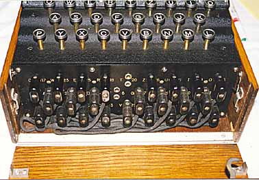
Each letter typed into the enigma machine's keyboard was converted to some other letter of the alphabet and displayed in a lighted window. Since the entire mechanism rotated each time a letter was entered, pressing the same letter three times could produce three different encodings. The encodings were produced by hard-wired code wheels and patch panels. The three code wheels could be mounted in a variety of positions and each one could be set to any letter of the alphabet. In addition, a patch panel on the front of the machine could be set up in many ways, making a vast number of combinations of cipher keys possible.
The Enigma cipher machine consists of a battery and a series of keys and
switches which determine which of the 26 light bulbs will illuminate one of
the 26 letters of the alphabet.
If you type the word ''HELLO'' on the keyboard (the plaintext message),
letters ''AZRWK'' (the ciphertext message) may be illuminated by the
light bulbs. The ciphertext message ''AZRWK'' is then sent by telephone or
radio to a receiving station and there an operator types ''AZRWK'' into
another Enigma machine which illuminates light bulbs ''HELLO'' (The original
plaintext message).
In order for this to work, the Receiving Enigma machine must be set to the
same STARTING POSITION as the Sending Enigma Machine was set to. Since there
are heptillions of possible starting positions, even if an enemy has an Enigma
machine, it is virtually impossible for them to decode the ciphertext since
they would not know the proper STARTING POSITION.
Here is how the initial starting position is set before sending the first
message of the day:
SETTING UP THE DAY'S STARTING POSITION:
1. Set the Sequence of Rotors ( Code Wheels ) on the rotor shaft.
(Set the Position of the 3 Numbered Rotors or Code Wheels from left to right
on the rotor shaft.)
(Any three of the 5 numbered rotors can be placed in any of the three
positions on the shaft.)
There are therefore 60 possible sequences of three rotors.
2. Set the Number or Letter Rings on each of the 3 Rotors (Code Wheels).
(Set the 'Ring Setting' of each Rotor or 'Code Wheel'.)
There are 26 possible settings on each of the three rotors.
This gives 26 to the third power = (17,576) possible settings.
3. Set the Number or Letter to be visible through the 3 windows at the
start of coding.
(Set the 'Starting Positions' or 'Ground Setting' of the three Rotors.)
There are 26 possible settings in each of the three windows.
This gives 26 to the third power = (17,576) possible settings.
4. Insert Double-Plug Cables into the Plugboard (Patch Panel).
(Set the Plug-in wire Connections on Plugboard.)
There are anywhere from 0 to 13 plug wires which can be inserted into any of
the 26 sockets.
This gives: Sum from p=0 to 13 of 26!/(26-2p)! x p! x 2 to the p power
= (532,985,208,200,576) possible settings.
Combining these possibilities give us a total of
26,672,901,348,424,004,787,290,112 or about 10 to the 26 power possibile
starting settings. (Other ways of calculating this figure produce different
totals.)
ENIGMA MACHINE WIRING DIAGRAM:
(Trace the battery voltage through the keyboard letter 'Q', the
plugboard, the rotors, the plugboard again, the keyboard again,
and ultimately to the light bulb letter 'W').
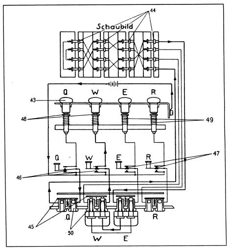 Wiring Diagram of the German Army Enigma Cipher Machine:
(Clockwise from top:)
(44) Rotor Contacts
(49) Lamp Contact Springs
(47) Key Contacts N. C.
(50) Jacks in Patch Panel
(45) Bypass Contacts for Unused Jack Panel Sockets
(46) Key Contacts N. O.
(48) Lamp Contacts
(43) Light Bulbs
ENIGMA MACHINE ROTOR DIAGRAM:

Enigma Rotors (Coding Cylinders)
(21a) Axle Shaft Collar
(24) Spring Stud for adjusting ring settings
(22) Retainer Spring for adjusting ring settings
(21) Axle Shaft
(23) Retainer Spring Button for adjusting ring settings
A short list of Internet Web Resources, Films, and Books devoted to the Enigma.
This video is also included in:
"THE STORY OF THE ENIGMA CD-ROM REFERENCE LIBRARY CD-ROM".
`
These exceptional films are among the most important discoveries of my career:
The two original German movie film clips show the Enigma actually
being used by German Soldiers.
Obviously the Germans did not want people to know that they were using
Enigmas for most of their secret communications so very few still
photographs of Enigmas in action have been found. Finding one is a
remarkable event. The discovery of these two original films is an even more
remarkable and important event.
I first saw tiny pieces of these movie clips in 2011 in the wonderful DVD:
"The Spies Who Lost the Battle of Britain: The Story of British Radar
and how the Germans Nearly Discovered it".
It is a very well researched and produced documentary of the
development and deployment of Radar in the early days of WW-2.
The DVD was filmed and published by Brian Marshall of boffinstv.co.uk and it is
sold by the Radio Society of Great Britain (RSGB) www.rsgb.org.
Brian was kind enough to track down the brief clips from NARA in his DVD
and he sent me more complete film segments. They are truly remarkable...
Thanks, Brian !
They are offered here as copyrighted .wmv files.
You may download them and view them but if you display or offer them to the
public in any form you must mention the www.w1tp.com/enigma museum
and the above information on the boffinstv.co.uk DVD.
FILM CLIP 1.
Luftwaffen Nachrichten Trupp (SdKfz82) from an Air
Reconnaisance Group and their Henschel Aircraft:
This original 31 second German film clip shows an Enigma being operated in the
field adjacent to a radio communications truck. It starts with a view of the
vertical antenna on top of its mast (Kurbelmast) and the coaxial cable to
the radio inside the communications truck. Then it shows the truck and the
German soldiers operating the Enigma. Finally it shows some views of
the parked Henschel aircraft. (File Name: enigop1.wmv / File Size: 1.6MB)
FILM CLIP 2.
Detailed Views of an Enigma in Action in a Wehrmacht
Nachrichten Trupp:
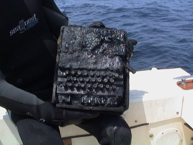
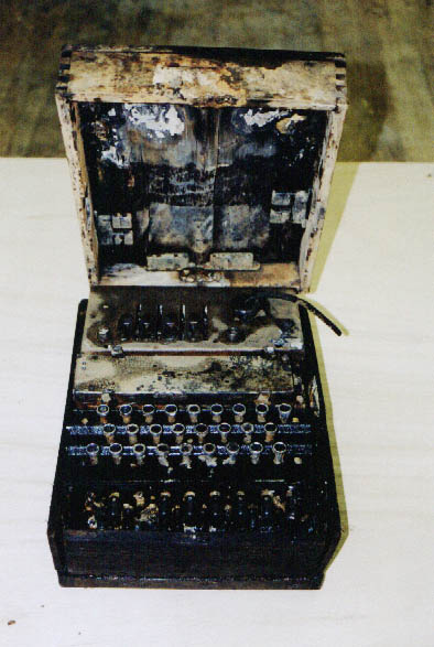
Here is an example of:
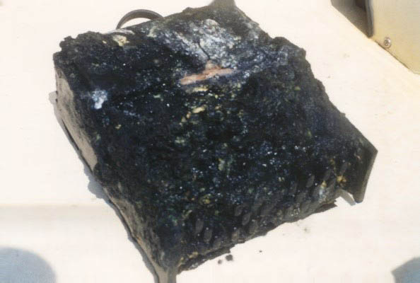
another marine Enigma that
was recovered from a submarine off the East coast of the United States in
2002.
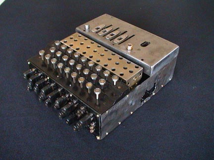
After careful cleaning and expert restoration much of
the dirt and corrosion has been removed and the machine begins to appear as it
once looked.
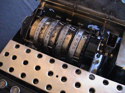
The internal mechanism and rotors, however, are still not
in very good condition.
These images are displayed with the permission of the divers who recovered the
machines and with the permission of Dr. David Hamer, the curator of the
website where they and many other photographs are displayed:
http://home.comcast.net/~dhhamer/u-85gal.htm
Here are some pictures and descriptions of the Enigma Machines that we have
found or seen over the years. For In-Depth coverage of Enigma History,
Technology, and Decoding, see the Enigma CD-ROM library and the
Enigma Book that are described at the top of this page.
Please click on this link:
THE VIRTUAL ENIGMA MUSEUM:
THE ENIGMA MUSEUM
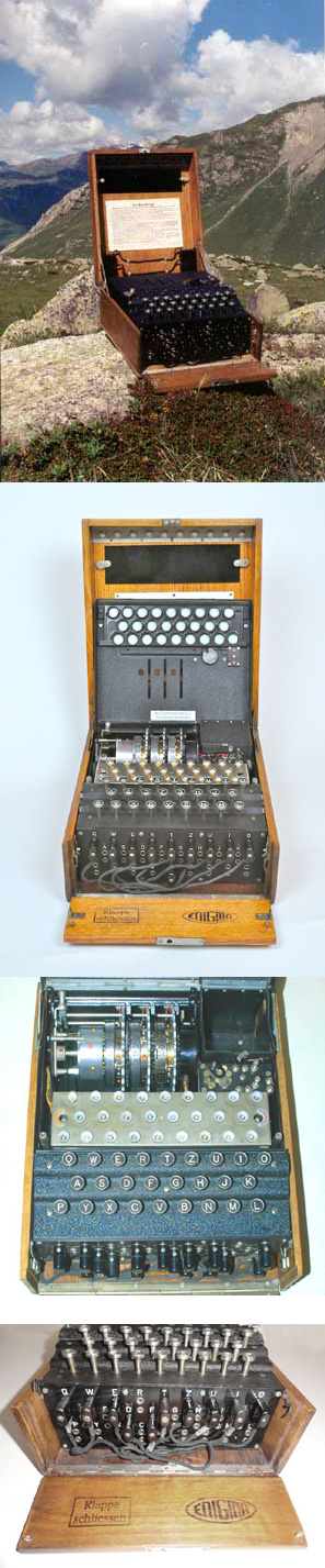
Although it is certainly not the first model of the Enigma machine, we will
start with the most widely known of the Enigma cipher machines, the German
Navy Kriegsmarine 4-rotor model. Then we will present some of the more widely
used Army and Air Force Enigmas as well as other cipher machines.
THE MUSEUM: GERMAN ENIGMA CIPHER MACHINES
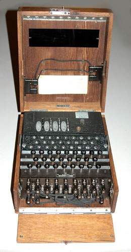
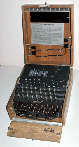
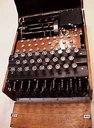
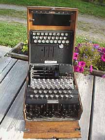
60 The GERMAN NAVY 4-ROTOR ENIGMA CIPHER MACHINE:(40KB)
This is one of the few surviving examples of the 4 rotor Marine Enigma
Machine. It is in reasonably good condition considering its age. The
following photographs show many views of the machine and its inner
workings.
Over 1000 additional Enigma photographs and diagrams are
contained in the CD mentioned above.
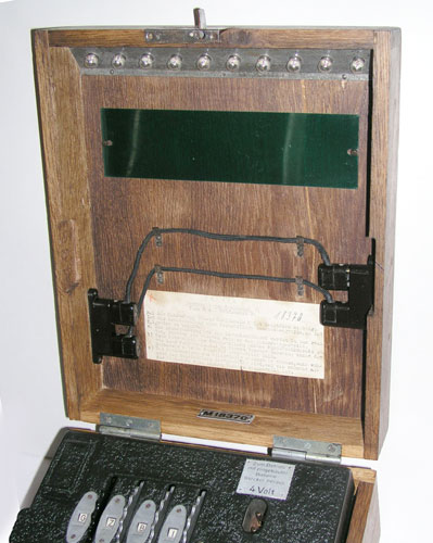
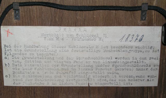
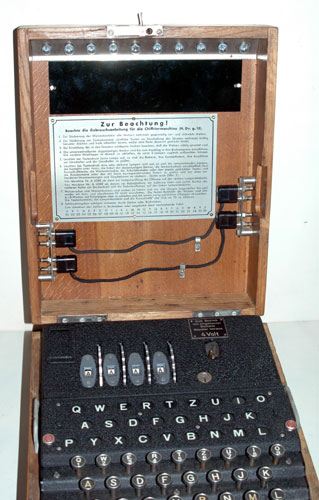
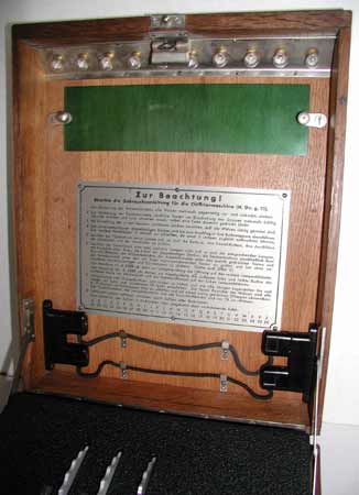
60a The inside of the cover showing the spare light
bulbs, the special filter plate, the instructions and two spare plug
cables:(37KB)

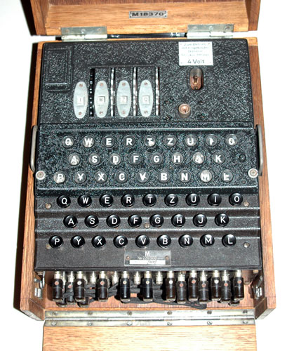
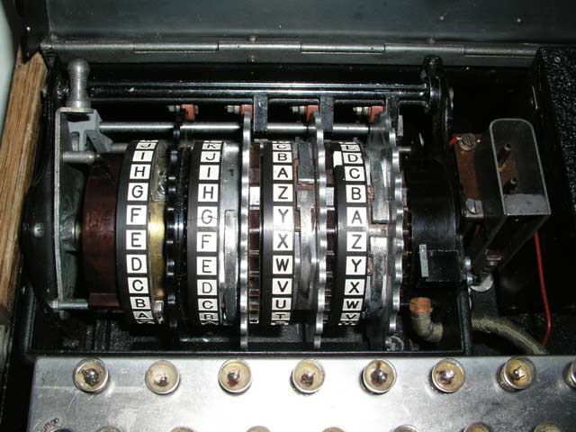
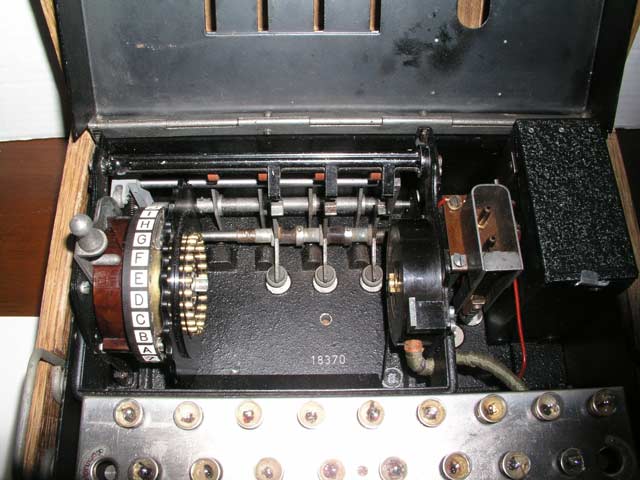
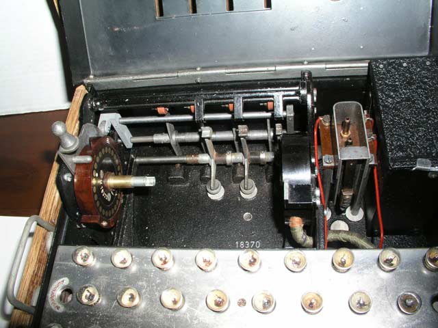
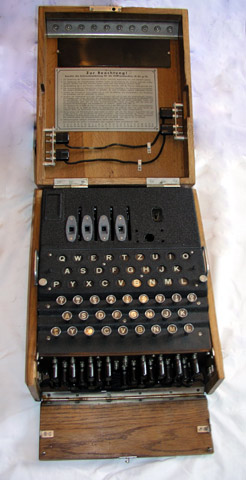
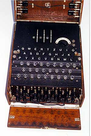
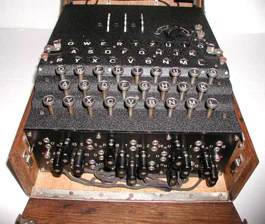
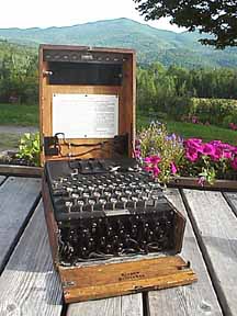
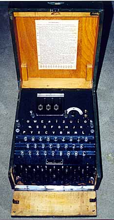
63 Another GERMAN NAVY 4-ROTOR ENIGMA CIPHER
MACHINE:(38KB) This 4 wheel Enigma cipher machine was found without its
rotors, reflector, and without some of the label tags.
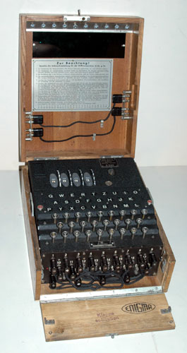
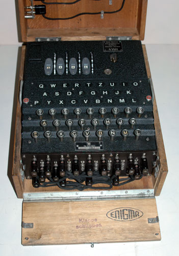
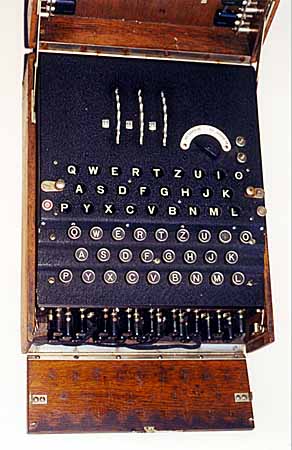
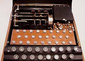
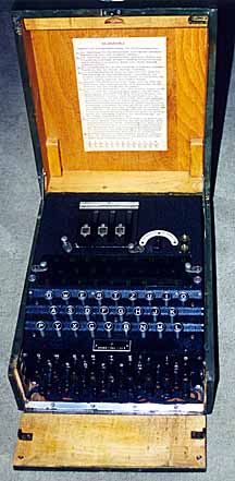
63a Overview of the Enigma showing the light filter in
place over the light bulbs:(38KB)
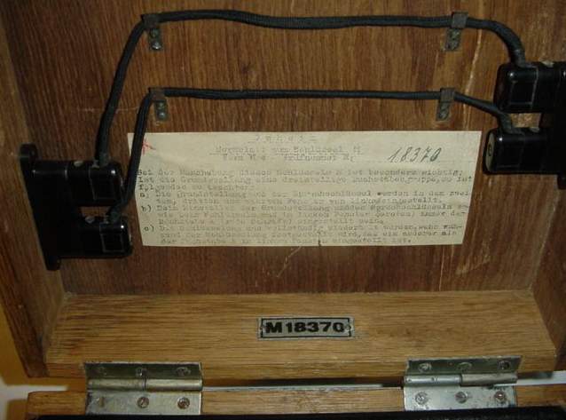
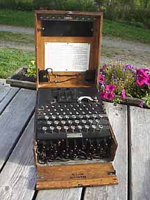
63b Inside view of the top cover showing the metal
instruction plate and the spare light bulbs and plug cables:(36KB)
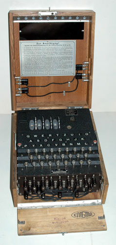
63c Closer view of the top panel:(40KB)
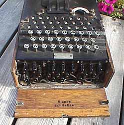
63d Closer view of the top panel with the light bulb
letter panel removed:(39KB)
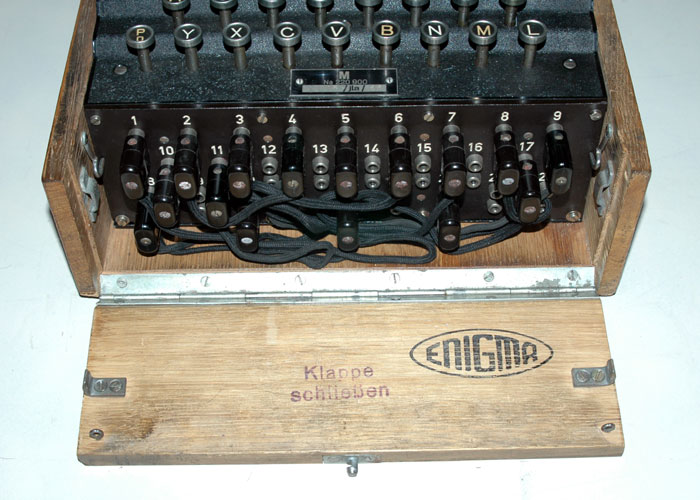
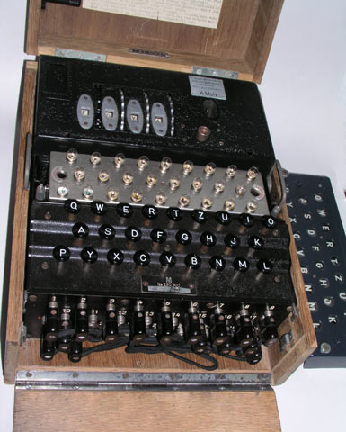
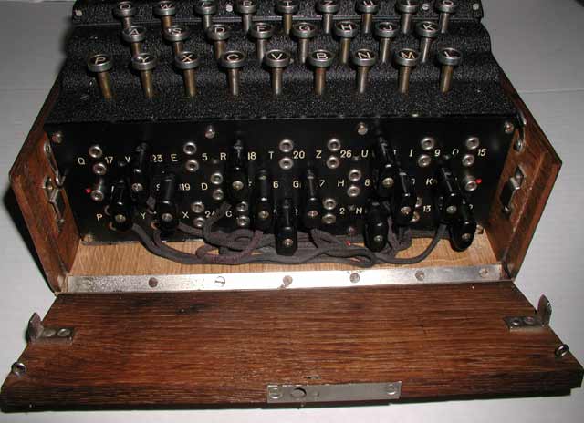
63e The plugboard:(58KB)
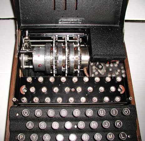
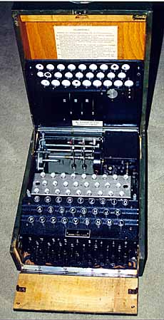
63f The top cover has been removed to show the light
bulbs, and the place where the rotors were mounted:(60KB)
63g The plastic bezel that shields the light bulbs and
mounts the transparent sheet carrying the letters:(33KB)
63h The place where the reflector and rotors are mounted.
Note that in the Navy M4 Enigma, there is no mechanism to rotate the leftmost
rotor with each keypress:(49KB)
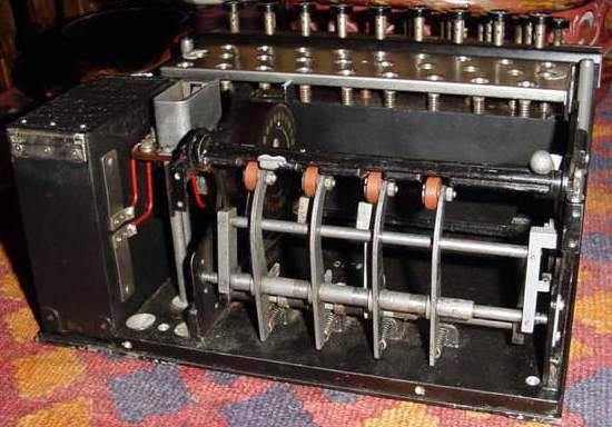
63i The place where the rotors are mounted showing the
input wheel and the arms that rotate the rotors with every keypress. Note
that in the Navy M4 Enigma, there is no mechanism to rotate the leftmost rotor
with each keypress:(52KB)
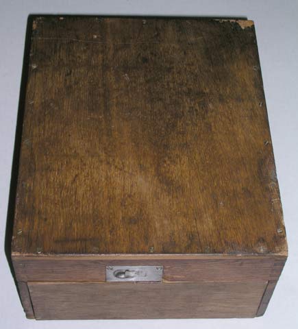
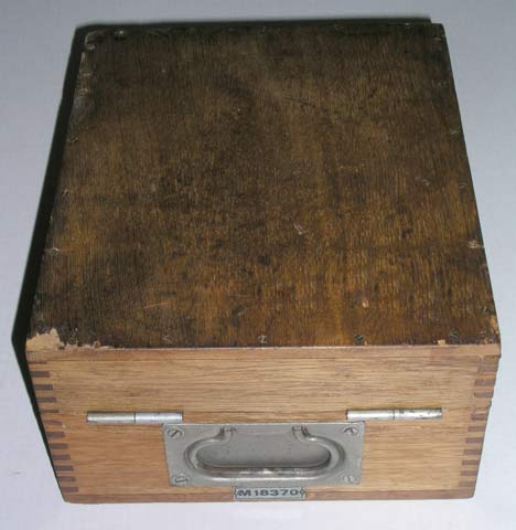
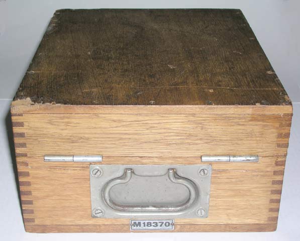
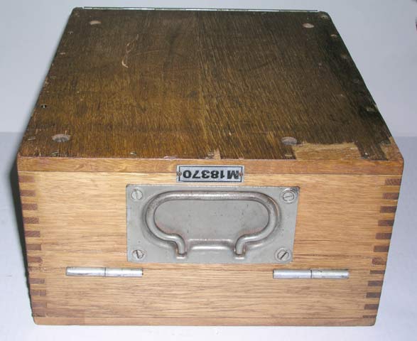
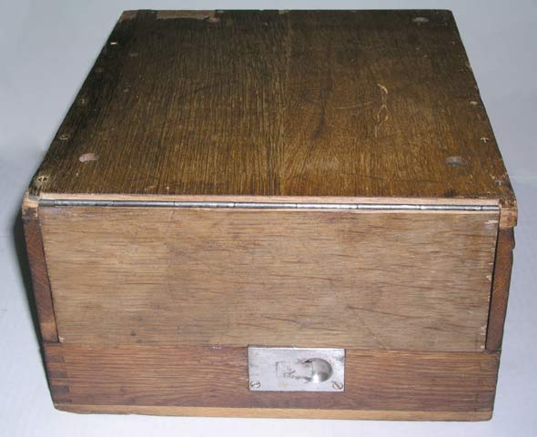
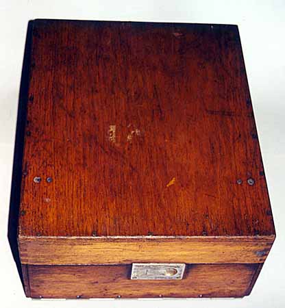
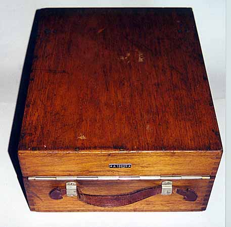
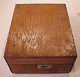
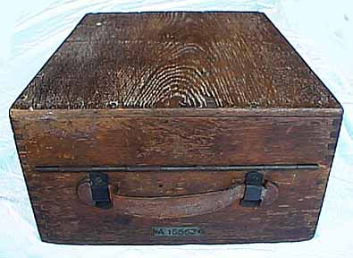
63j The top front of the wooden box:(33KB)
63k The top back of the wooden box showing the carrying
handle:(53KB)
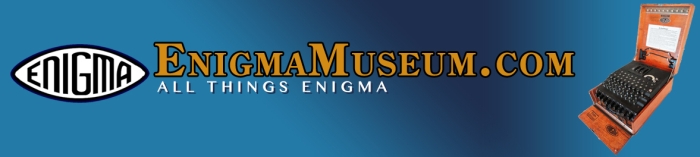
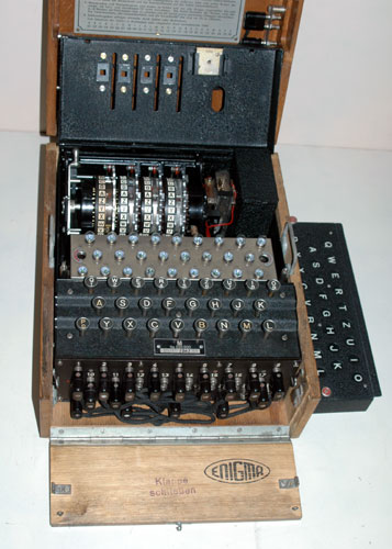
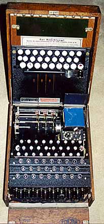
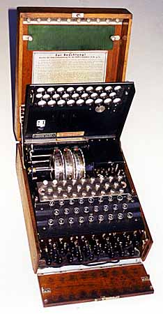
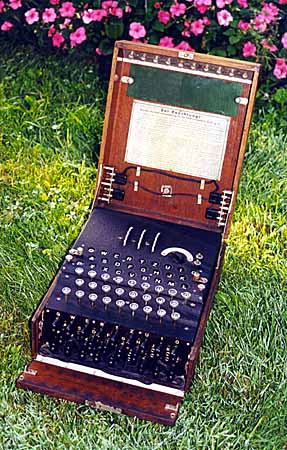
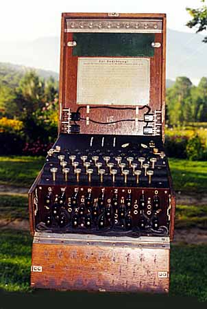
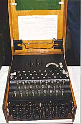
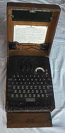
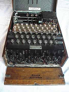
80 PRE-WW-2 * GERMAN ENIGMA CIPHER MACHINE:(25KB) This
three code wheel cipher machine called the "Enigma" was manufactured from the
early 1930's throughout World War II. The code was broken by the Poles whose
work helped the Allied forces develop strategies and machines which allowed
them to read many important German messages during the war. Note: the word
cipher is also spelled cypher which is a primarily British variant.
A team of codebreakers working at Bletchley Park in England was able to decode
most of the enigma-coded messages used by the German army even though the
Germans changed the settings of the machine. The code name for the
deciphering operation was "Ultra".
Each letter typed into the enigma machine's keyboard was converted to some
other letter of the alphabet and displayed in a lighted window. Since the
entire mechanism rotated each time a letter was entered, pressing the same
letter three times could produce three different encodings. The encodings
were produced by hard-wired code wheels and patch panels. The three code
wheels could be mounted in a variety of positions and each one could be set to
any letter of the alphabet. In addition, a patch panel on the front of the
machine could be set up in many ways, making a vast number of combinations of
cipher keys possible.
This is an early pre-WW-2 version manufactured in 1937 and later used by the
German Army.
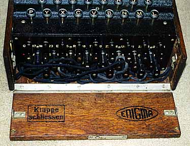
80a This is a closeup of the patch panel or
''steckerboard'':(34KB)
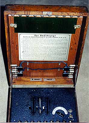
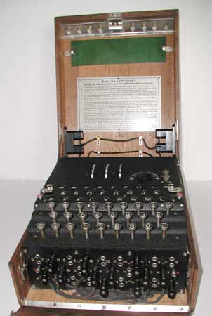
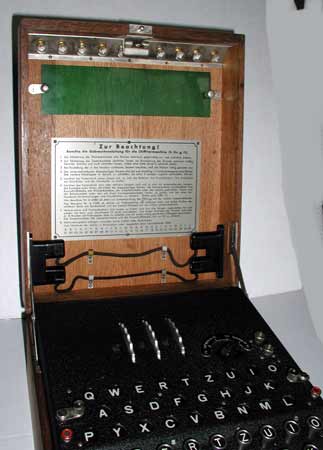
80b This is a closer view of the inside of the top cover
showing the instructions:(33KB)
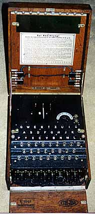
80c This is a view with the top of the machine open
showing the light bulbs and battery case:(31KB)
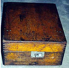
80d This is a view with the cover closed: (24KB)
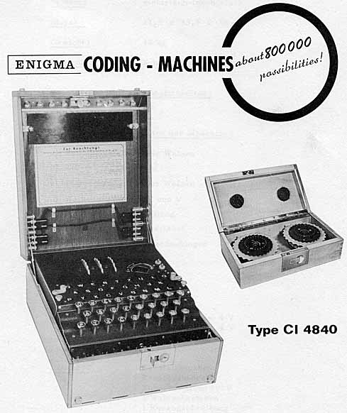
80e This is the front page of the English version of the
advertising brochure:(44KB)
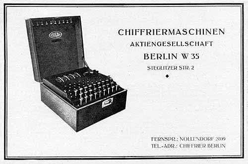
80f This is the front page of the instruction booklet of
an earlier version without steckerboard:(26KB)
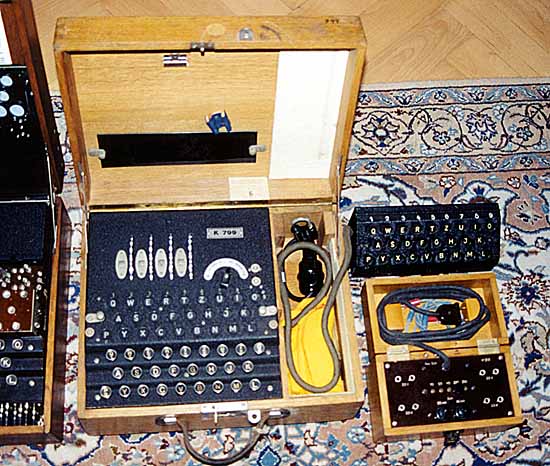
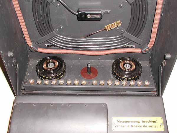
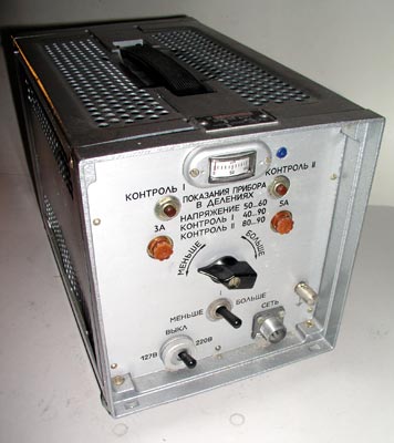
85 RARE 'K' - MODEL ENIGMA CIPHER MACHINE ( U. S. CODENAME
'INDIGO' ) WITH CODE WHEELS AND ADJUSTABLE REFLECTOR :(78KB)
This rare model of the enigma cipher machine has four adjustable wheels. The
right three code wheels (German 'walze') are similar to the standard enigma
machine wheels and the left wheel is actually a completely adjustable
reflector (German 'umkehrwalze') which can be set to any one of the 26
possible letters. The machine was also supplied with an external and internal
display as well as a multiple-voltage power converter transformer in a
separate box which converted voltages ranging from 110 - 250 Volts, AC to the
required 3.5-volts to operate the lamps. The remote display made it possible
for the officer-in-charge to read the decoded text without the cipher machine
operator being able to see it. This was useful for top-secret messages.
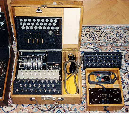
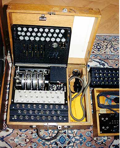
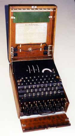
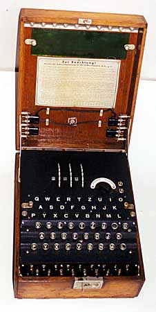
85a A view of the K Enigma with cover open:(70KB)
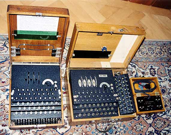
85b A view of the K Enigma next to a WW-II German
Army Enigma for size comparison:(72KB)
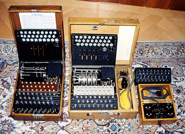
85c A view of the K Enigma next to a WW-II German
Army Enigma with top covers open for size comparison:(78KB)
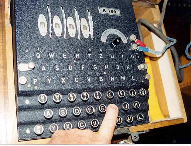
85d A closer view of the K Enigma with 'H' key pressed on
keyboard and 'X' key illuminated in the light panel:(75KB)
85e A closer view of the K Enigma with cover
open:(57KB)
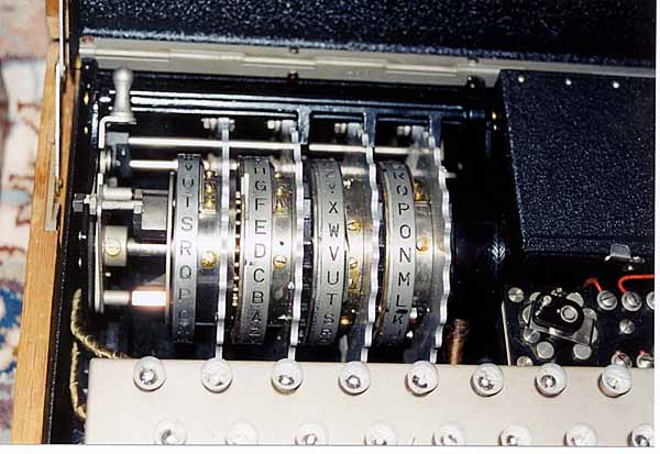
85f A closer view of the 3-rotors of the K Enigma
on the right and reflector on the left:(48KB)
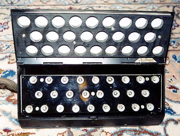
85g A closer view of the remote display light
panel:(45KB)
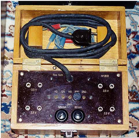
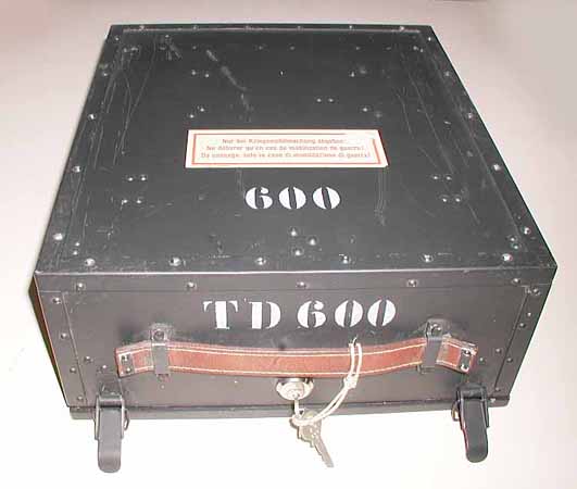
85h A closer view of the power transformer
box:(59KB)
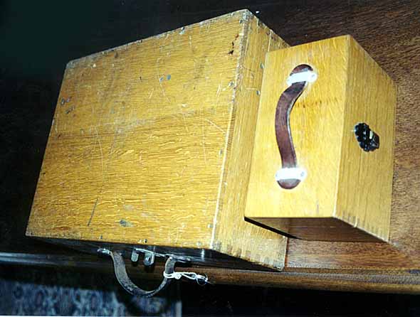
85i A view of the K Enigma and power converter
with wooden covers closed:(38KB)
90 GERMAN ARMY WW-II ENIGMA CIPHER MACHINE WITH CODE
WHEELS:(20KB)This three code wheel cipher machine called the "enigma" was
manufactured from the early 1930's throughout World War II. The code was
broken by the Poles whose work helped the Allied forces develop strategies and
machines which allowed them to read many important German messages during the
war.
A team of codebreakers working at Bletchley Park in England was able
to decode most of the enigma-coded messages used by the German army even
though the Germans changed the settings of the machine. The code name for the
deciphering operation was "Ultra".
Each letter typed into the enigma
machine's keyboard was converted to some other letter of the alphabet and
displayed in a lighted window. Since the entire mechanism rotated each time a
letter was entered, pressing the same letter three times could produce three
different encodings. The encodings were produced by hard-wired code wheels
and patch panels. The three code wheels could be mounted in a variety of
positions and each one could be set to any letter of the alphabet. In
addition, a patch panel on the front of the machine could be set up in many
ways, making a vast number of combinations of cipher keys possible. (sold,
02/14/1999)
90a This is another view of the open
machine:(23KB)
90b A front view of the Enigma
with cover closed:(26KB)
90c A rear view of the
Enigma with cover closed:(28KB)
90d A closer view
of panel of the Enigma showing the plugboard:(33KB)
90e Another closer view of panel of the
Enigma:(33KB)
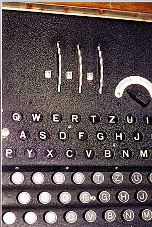
90f A MUCH closer view of panel of
the Enigma showing the wheel numbers:(53KB)
90g A view of the Enigma with panel open
showing the three code wheels:(27KB)
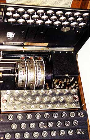
90h A very close view of the Enigma
with panel open showing the three code wheels:(40KB)
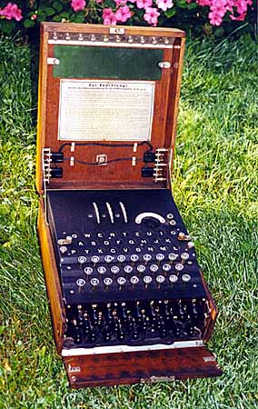
90i A view of the Enigma in scenic
surroundings:(53KB)
90j Another view of the Enigma in scenic
surroundings:(55KB)
90k A closer view of the Enigma in scenic
surroundings showing the plugboard:(31KB)
92 GERMAN ARMY WW-II ENIGMA CIPHER MACHINE WITH
ALL FIVE MATCHING ROTORS:(16KB)This German Army model Enigma machine is
in excellent condition as you can see from these pictures. It is shown
with a complete set of rotors I, II, and III as well as the two
additional rotors, IV and V which were interchanged with the three
standard rotors to add complexity to the code settings.
92a A closer view of the inside of the top of the
box showing the spare light bulbs, spare plugboard cables, and the
instruction plate:(17KB)
92b A much closer view of the inside of the top of the
box showing the spare light bulbs, spare plugboard cables, and the
instruction plate:(18KB)
92c A closer view of the front of the Enigma
showing the plugboard, keyboard, light panel, and rotor thumbwheels:
(42KB)
92d A much closer view of the front of the Enigma
showing the plugboard:(37KB)
92e A view of the code wheels with the cover
raised:(37KB)
92f A much closer view of the code wheels with the cover
raised:(43KB)
92g A view of the Enigma with the
code wheels removed showing the reflector on the left:(42KB)
92h A view of the 5 code wheels:(24KB)
92i A different view of the 5 code wheels:(16KB)
92j A view of the top of the Enigma machine with the
cover closed:(16KB)
92k A view of the bottom of the Enigma machine with the
cover closed:(16KB)
92m A view of the front of the Enigma machine with the
cover closed showing the latch:(8KB)
92n A view of the side of the Enigma machine with the
cover closed:(6KB)
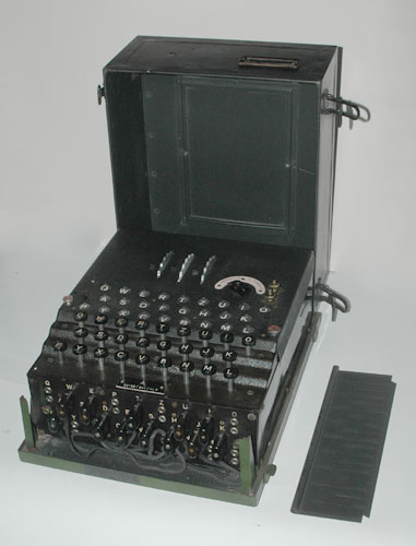
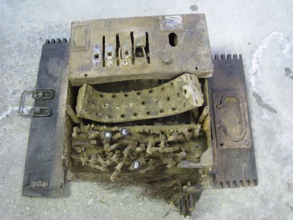
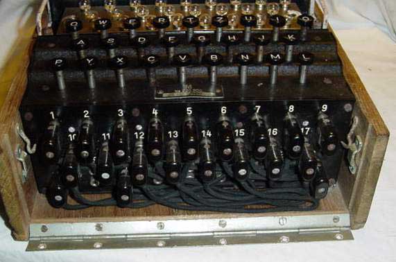
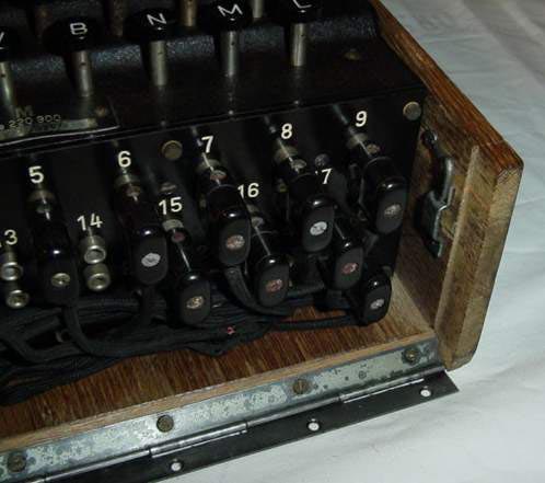
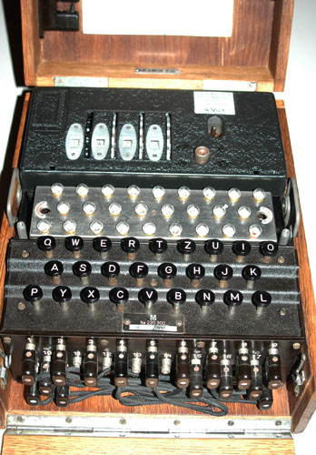
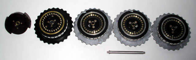
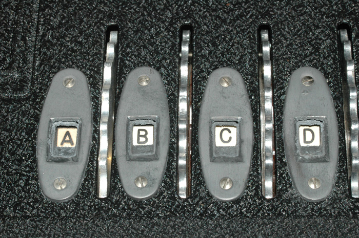
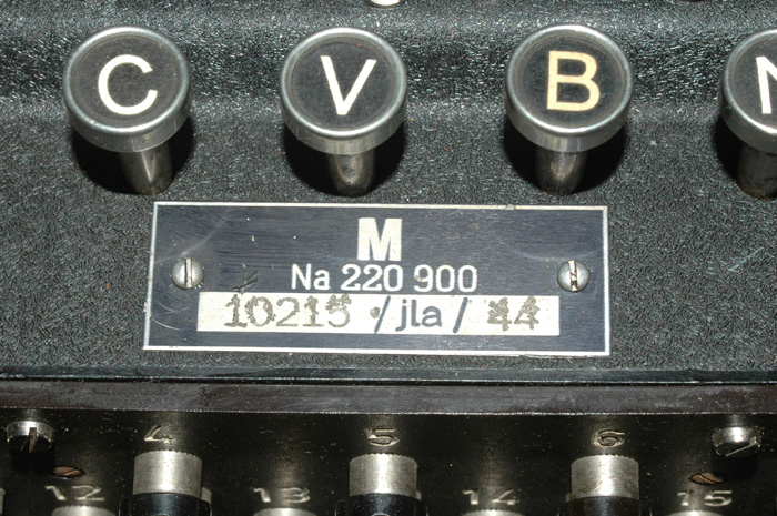
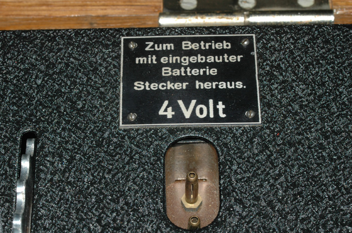
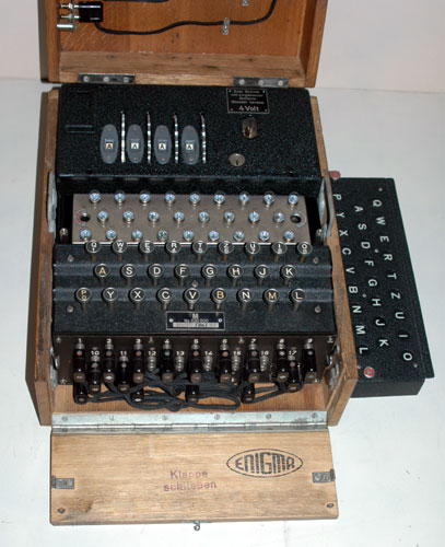
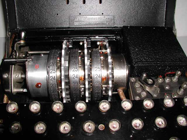
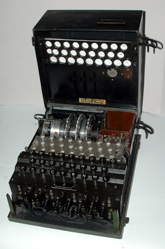
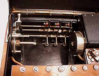
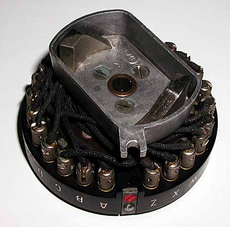
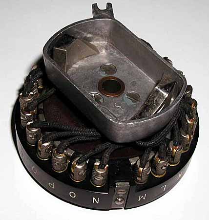
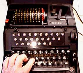
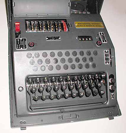
95 GERMAN AIR FORCE (LUFTWAFFE)
3-ROTOR WW-II ENIGMA CIPHER MACHINE IN METAL CASE:
This three rotor German Air Force Enigma cipher machine was used during WW-II.
Many of the Air Force Enigmas were enclosed in these rugged metal cases. The
following pictures show various views of the machine.
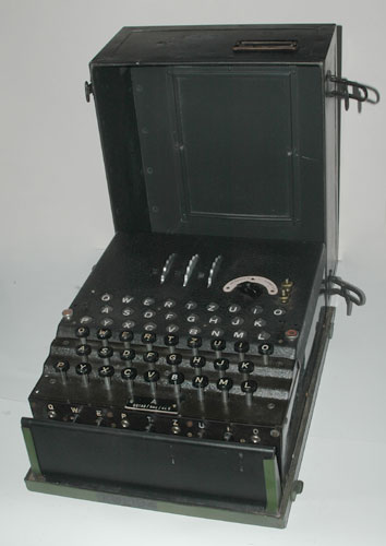
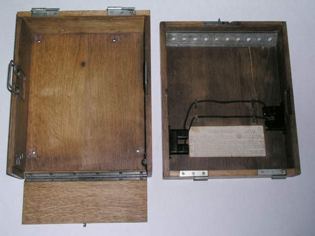
The Air Force Enigma with the special
metal protective plate in place over the plugboard panel.
This metal plate prevented the wires from
being pinched or damaged when the metal cover was placed over the
Enigma:
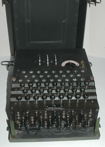
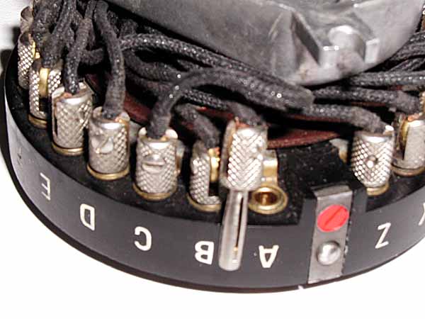
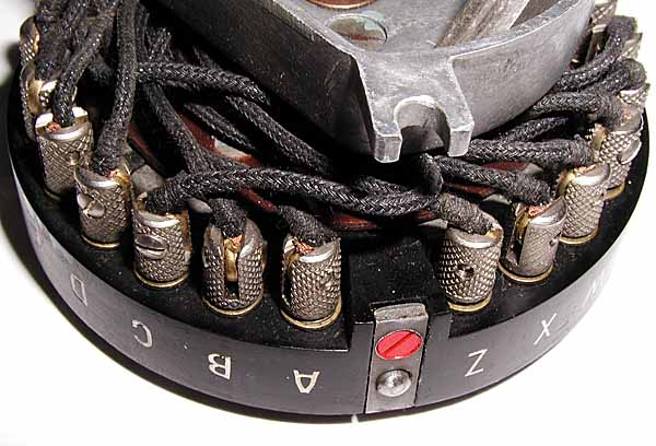
A closer view of the top of the Enigma panel:
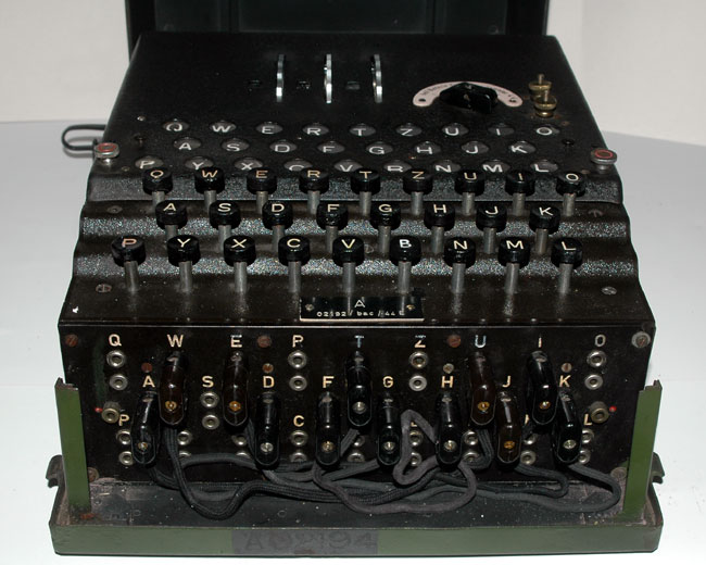
A closer view of the plugboard and keyboard:
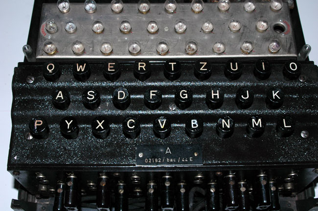
A closer view of the keyboard:
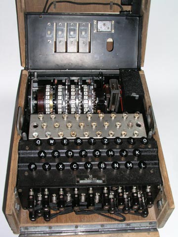
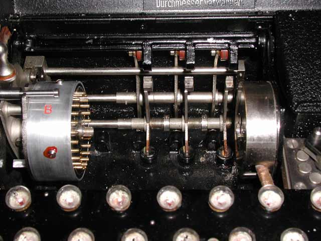
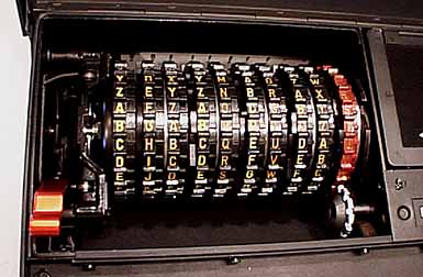
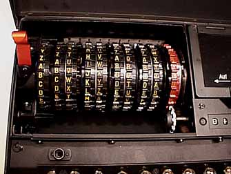
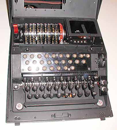
The Enigma with the top panel open showing the light
bulbs, rotors, and battery box:
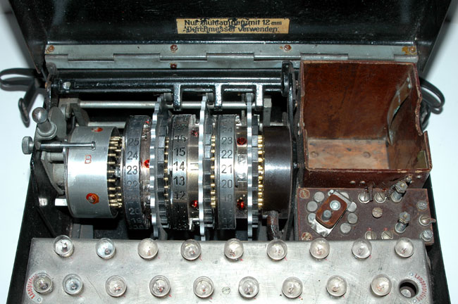
A closer view of the Rotors, the light bulbs, and
the battery box:
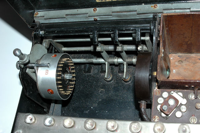
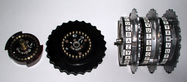
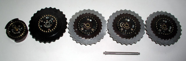
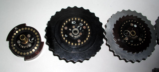
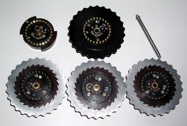
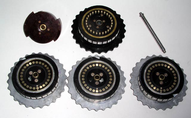
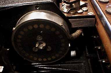
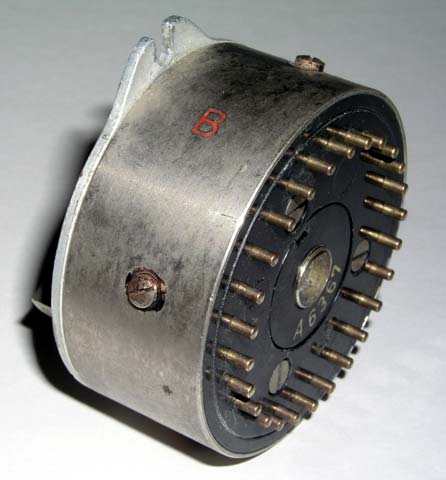
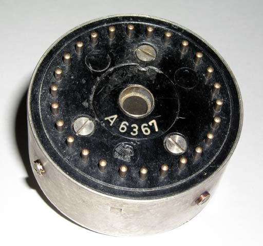
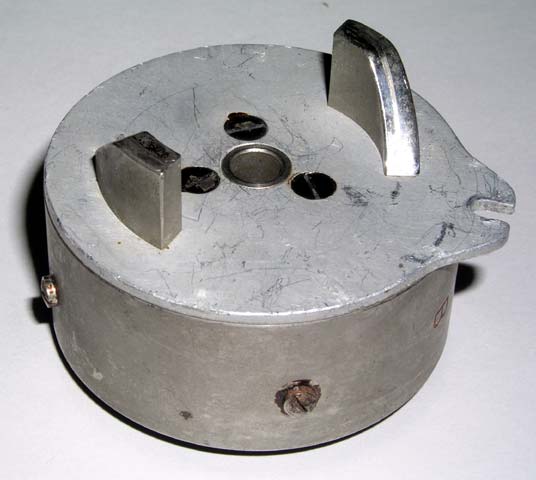
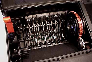
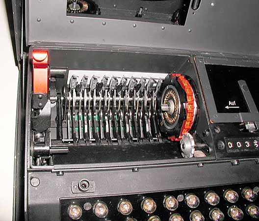
The reflector after the rotors have been removed:
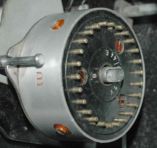
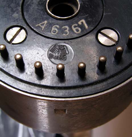
A closer view of the "B" reflector that carries number
A01400/44E:
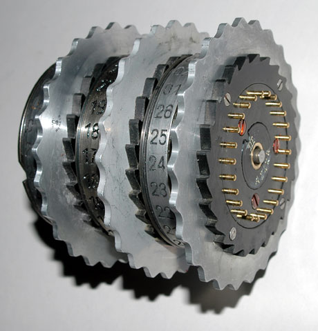
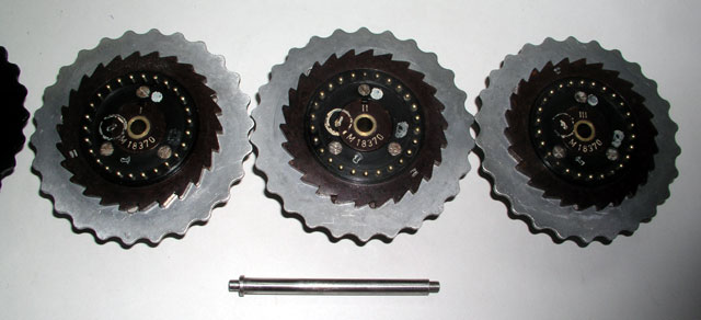
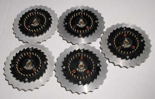
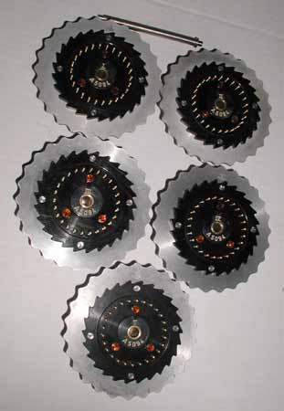
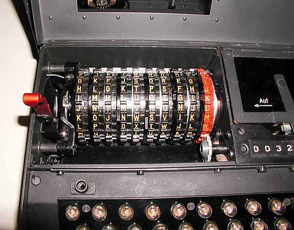
The rotors on their rotor shaft:
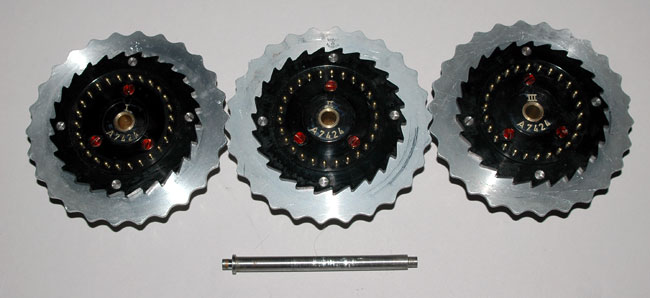
The three rotors numbered: I, II, and III:
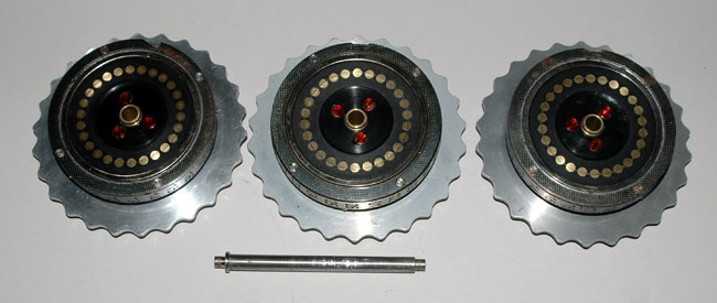
The other side of rotors I, II, and III:
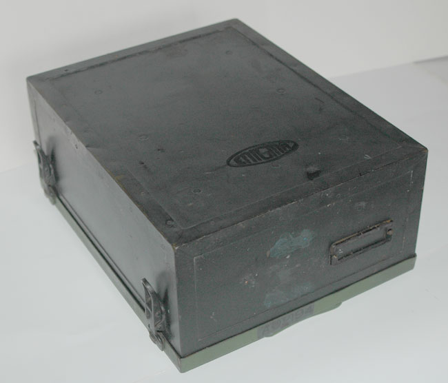
The outside of the top of the
case:
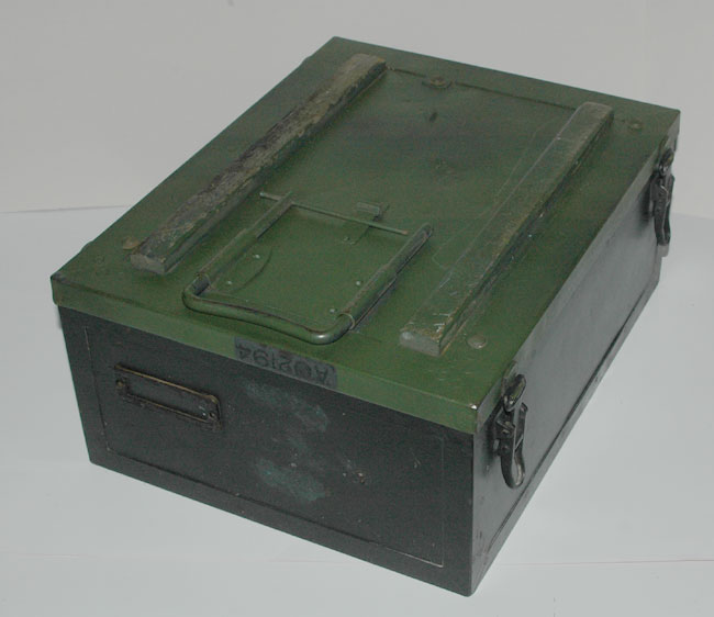
The outside of the bottom of the
case:
100 GERMAN ARMY WWII ENIGMA CIPHER MACHINE:(16KB)
This three code wheel cipher machine called the "enigma" was
manufactured from the early 1930's throughout World War II. The code
was broken by the Poles whose work helped the Allied forces develop
strategies and machines which allowed them to read many important
German messages during the war.
A team of codebreakers working at Bletchley Park in
England was able to decode most of the enigma-coded messages used
by the German army even though the Germans changed the settings
of the machine. In addition, a patch panel on the front of the machine could
be set up in many ways, making a vast number of combinations of cipher keys
possible. (sold, 02/14/1999)
100a This is a closeup of the patch
panel:(34KB)
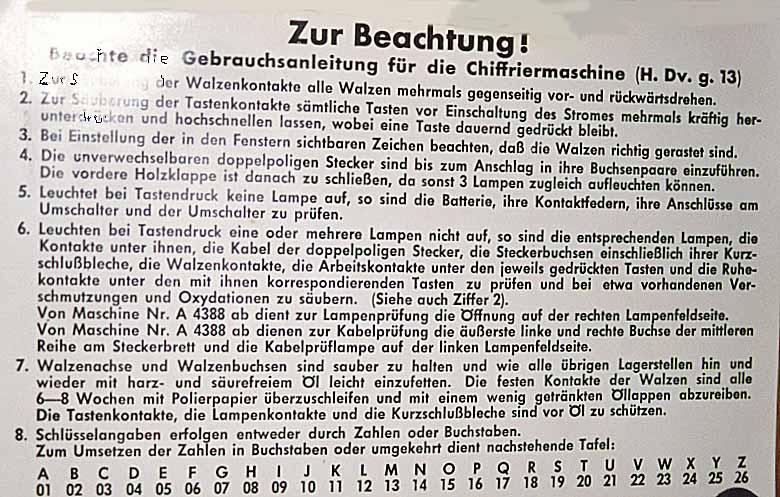
100b This is a photograph of the instructions
mounted inside the top cover:<107KB)
100c A view of the Enigma with cover
closed:(16KB)
100d A view of the inside of the Enigma:(18KB)
100e A closer view of the inside of the
Enigma:(26KB)
100f A view of the mechanism which rotates the
wheels:(24KB)
100g A view of the electrical contacts to the
wheels:(18KB)
Here are some views of ANOTHER GERMAN ARMY WW-II ENIGMA CIPHER MACHINE.
This is a slightly earlier model with the pastic cover for the rotors which
are also not present.
101 An overall view of the enigma machine:(17KB)

101a A closer view of the top of the enigma
machine:(26KB)
101b A closer view of the top of the enigma machine
(cover open):(27KB)
101c A view of the enigma machine with case
closed:(23KB)
101d An overview of the enigma machine in scenic
surroundings:(21KB)
101e A closer view of the enigma machine in scenic
surroundings:(19KB)
101f A closer view of the enigma machine in scenic
surroundings:(19KB)
101g A closer view of the enigma machine plug
panel:(24KB)

101h A closer view of the enigma machine with cover
open:(21KB)
Here are some views of ANOTHER GERMAN ARMY WW-II ENIGMA CIPHER MACHINE.
This is a slightly earlier model contained in a green-painted case.
It also has the pastic cover for the rotors which
are not present.
103 An overall view of the enigma machine:(27KB)
103a Another overall view of the enigma
machine:(24KB)
103b A view with the internal cover open showing the
light bulbs and battery box:(30KB)
103c A view of the enigma machine with case
closed:(15KB)
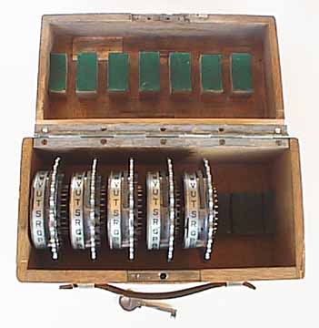
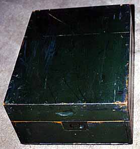
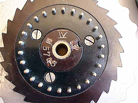
105 BOXED SET OF ORIGINAL WW-II MARINE ENIGMA CIPHER
MACHINE CODE WHEELS:(21KB)
Here is a boxed partial set of the original code wheels (German 'walze')for
a marine enigma machine in the original carrying box. The box is marked as
the property of the German Marine High Command in Norway.
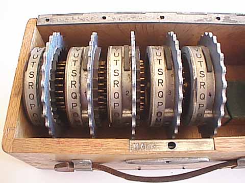
105a A closer view of the 5 code wheels in the
box:(32KB)
105b A view of the sides of all 5 code
wheels:(29KB)
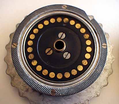
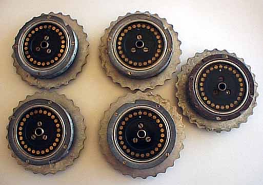
105c A view of the flat contacts of a code
wheel:(26KB)
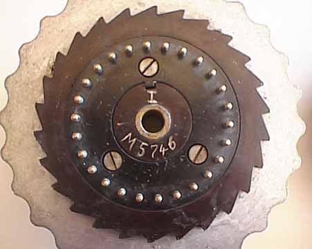
105d A view of the pin contacts on wheel number
1:(21KB)
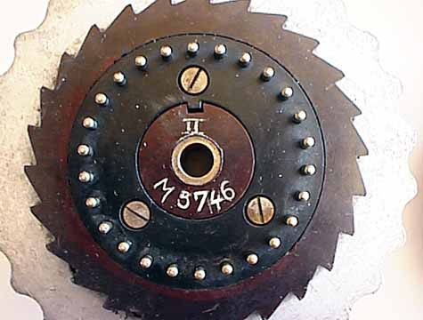
105e A view of the pin contacts on wheel number
2:(27KB)
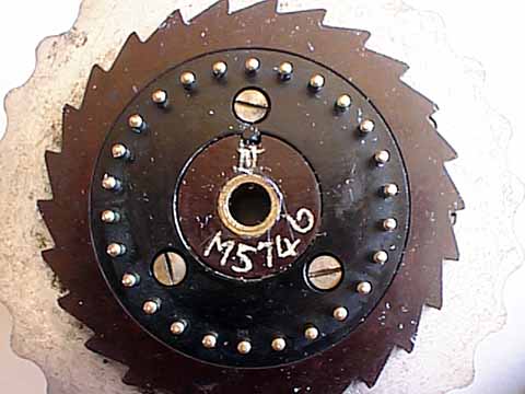
105f A view of the pin contacts on wheel number
3:(28KB)
105g A view of the pin contacts on wheel number
4:(30KB)
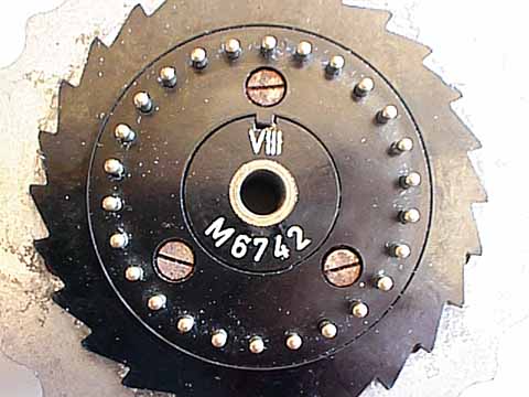
105h A view of the pin contacts on wheel number
8:(31KB)
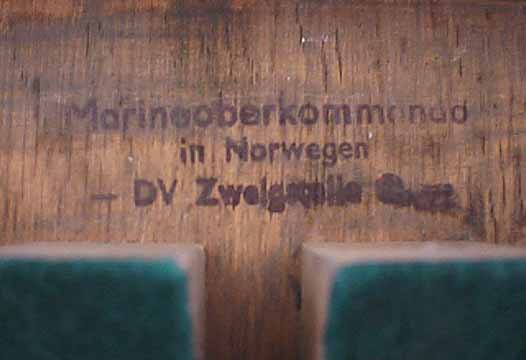
105i A close view of the Marine High Command
label:(17KB)
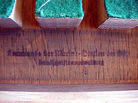
105j A close view of the Marine Label:(31KB)
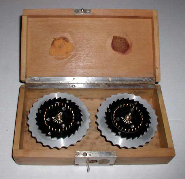
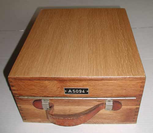
106 CLASSIC HORIZONTALLY BOXED BOXED SET OF WW-II ARMY
ENIGMA CIPHER MACHINE CODE WHEELS (ROTORS):(28KB) The German Army Enigma
machines had places for three rotors I, II, and III. The machines were also
supplied with two additional rotors, numbers IV and V which were stored in a
special box to allow them to be carried around with the machine without
damaging them. This is the box that was classically supplied to protect and
transport the additional wheels.
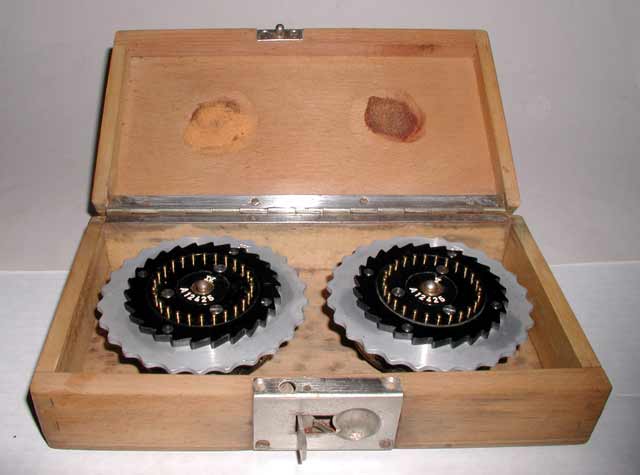
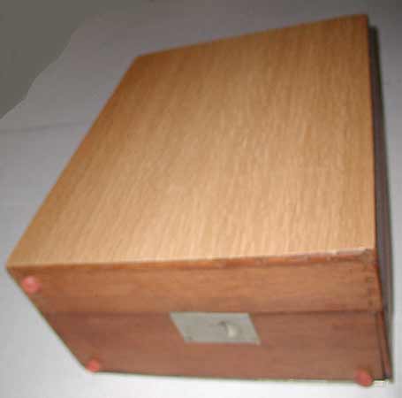
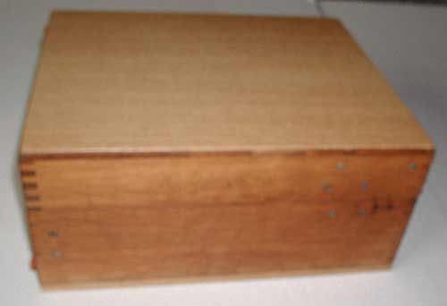
106a A slightly different perspective photo of the box
with the two rotors:(24KB)
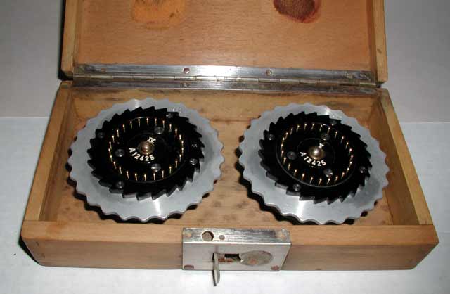
106b A closer view of the two rotors in the box, showing
the numbers IV and V:(23KB)
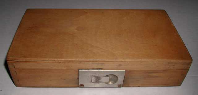
106c A view of the front of the box in the closed
position showing the latch:(9KB)
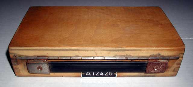
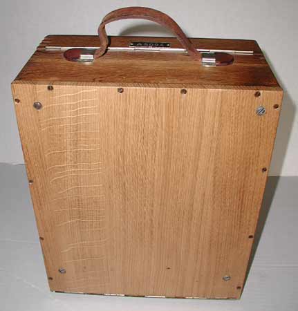
106d A view of the back of the box in the closed position
showing the handle and serial number:(13KB)
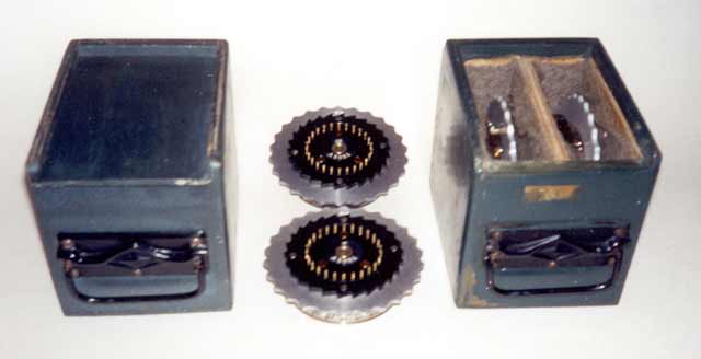
107 VERY RARE VERTICALLY BOXED SETS OF ORIGINAL WW-II
ARMY ENIGMA CIPHER MACHINE CODE WHEELS (ROTORS):(15KB)
The Army Enigma machines had places for three rotors I, II, and III. The
machines were also supplied with two additional rotors, numbers IV and V which
were stored in a special box to allow them to be carried around with the
machine without damaging them. The usual box stores the rotors in a
horizontal position but these very unusual boxes store the rotors in a
vertical position.
108 AN EXCEPTIONALLY RARE PROGRAMMABLE D-REFLECTOR
WHEEL (GERMAN 'UMKEHRWALZE-D') FOR WW-II GERMAN ARMY ENIGMA CIPHER
MACHINES:(27KB)This is the first fully
programmable reflector wheel that I have seen. It is called the
D-reflector. It was used in the German Army (Heer) Enigma machine and it
was first observed on January 2, 1944 in Norwegian traffic. It has 25
wires and tiny plugs and each wire can be plugged into each
of the 25 positions.
108a Another view of the D-reflector:(28KB)
108b A view of the D-reflector with cover
removed:(32KB)
108c The other side of the D-reflector with cover
removed:(31KB)
108d A close-up view of the plugs and
wires:(36KB)
108e Another close-up view of the wires:(54KB)
109 THE STANDARD GERMAN ENIGMA 'B' REFLECTOR WITH AN
UNUSUAL INSPECTOR'S STAMP:(28KB)
This is the standard version of the reflector used in the German
Enigmas. Each inspector was issued an unique inspection stamp and this one
shows a bird with its wings angling downwards while the most common stamps
have the wings in an horizontal orientation.
109a Another view of the 'B' Reflector:(39KB)
109b Another view of the 'B' Reflector:(30KB)
109c A Close view of the inspector's stamp on the 'B'
Reflector:(36KB)
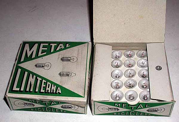
110 HARD-TO-FIND LIGHT BULBS FOR GERMAN ENIGMA
MACHINES:(40KB)Here are pictures of two boxes of the original
light bulbs for the German enigma machines.
These bulbs are flattened so that they do not come into contact with the
plastic numerals in the display. Using round light bulbs usually
results in cracking the plastic numerals in the display.
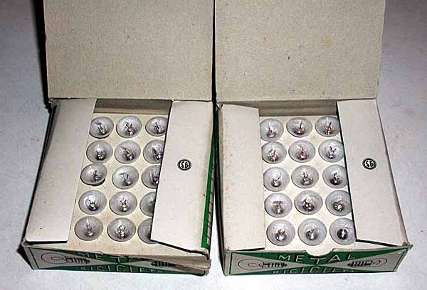
110a Another view with both boxes open:(37KB)
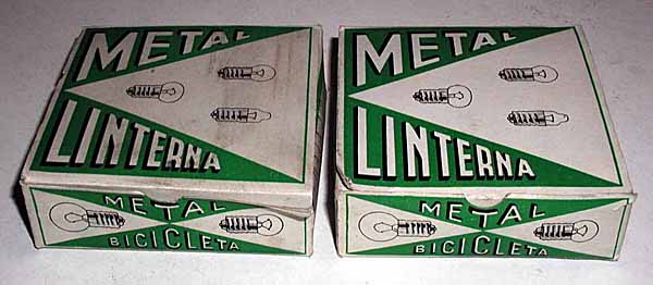
110b Another view with both boxes closed:(33KB)
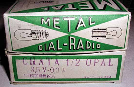
110c A view of the label on the side of the
boxes:(35KB)
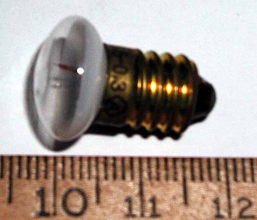
110d A close-up view of one light bulb:(27KB)
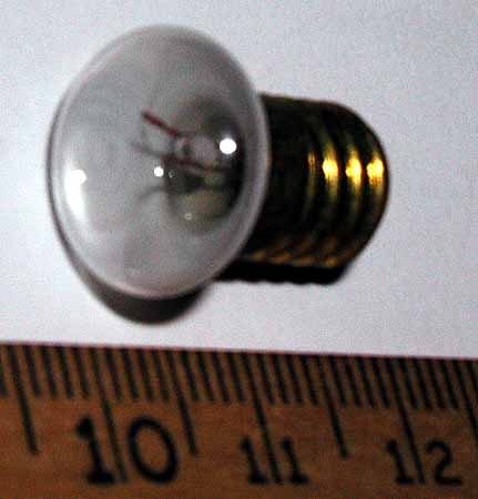
110e Another close-up view of the bulb:(19KB)
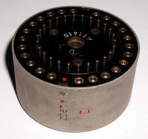
112 A SET OF RARE ENIGMA ROTORS WITH BLACK BAKELITE
THUMBWHEELS:(15KB)These rotors are unusual because they
have a black bakelite thumbwheel instead of the metal thumbwheel
found on most rotors.
112a A view of the other side of the rotor:(19KB)
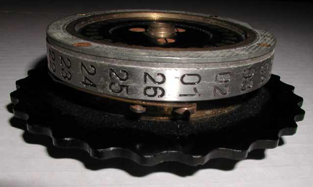
112b A view of the numbers and the ring setting
adjustment on the rotor:(18KB)
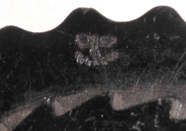
112c A closeup view of the German eagle emblem stamped
into the bakelite thumb wheel:(18KB)
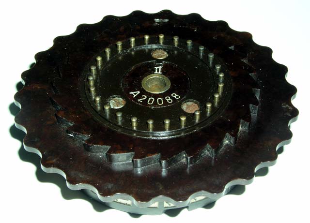
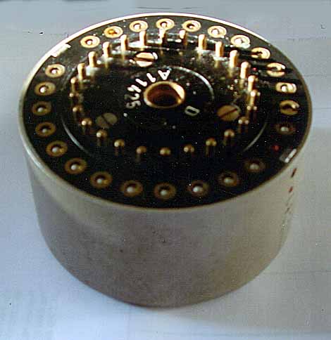
113 AN UNUSUAL ENIGMA ROTOR WITH A BROWN BAKELITE
THUMBWHEEL AND BROWN BAKELITE NUMBER WHEEL:(37KB)David Hamer has told me
that the Germans began using more and more Bakelite in the construction of
their Enigma Rotors as the war progressed because of a shortage of metal in
Germany. This rotor has both the thumbwheel and the numbers made from moulded
Bakelite.
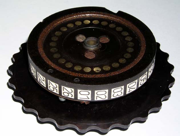
113a Another view of the Brown Bakelite Enigma
Rotor:(37KB)
113b Another view of the Brown Bakelite Enigma
Rotor:(39KB)
113c A Close view of the inspection stamp on the
Brown Bakelite Enigma Rotor:(50KB)
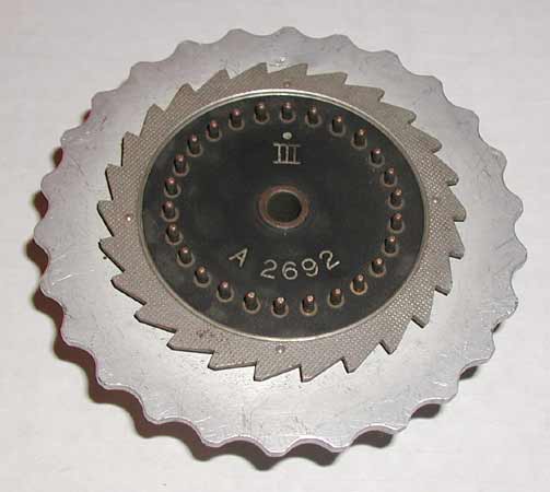
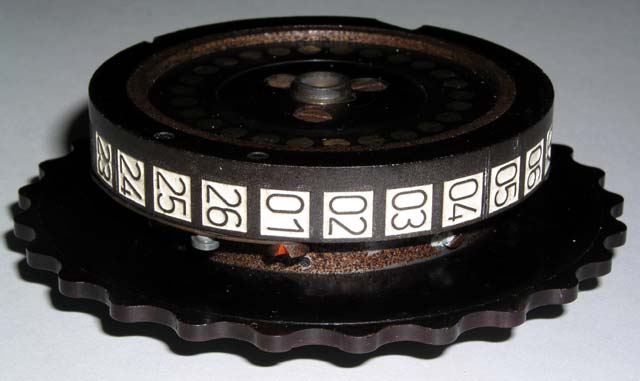
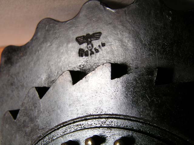
114a A SET OF RARE ENIGMA ROTORS WITH METAL COGS UNUSUAL
NUMBERING, AND AN UNUSUAL GERMAN EAGLE INSPECTOR'S EMBLEM:(19KB)This
unusual set of Enigma rotors came from Italy. The rotors have metal cog
wheels, an unusual looking dot over the roman numbers indicating the rotor
number, and an unusual inspector's emblem. Each inspector was issued an
unique inspection stamp and this one shows a bird with its wings angling
downwards while the most common stamps have the wings in an horizontal
orientation.
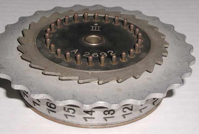
114b A different view showing the metal cog
wheel:(24KB)
114c A view of the other side of the rotor
showing the numbers and the ring setting detent:(18KB)
114d A view of the unusual eagle symbol:(14KB)
114e Another view of the unusual eagle symbol:
(15KB)
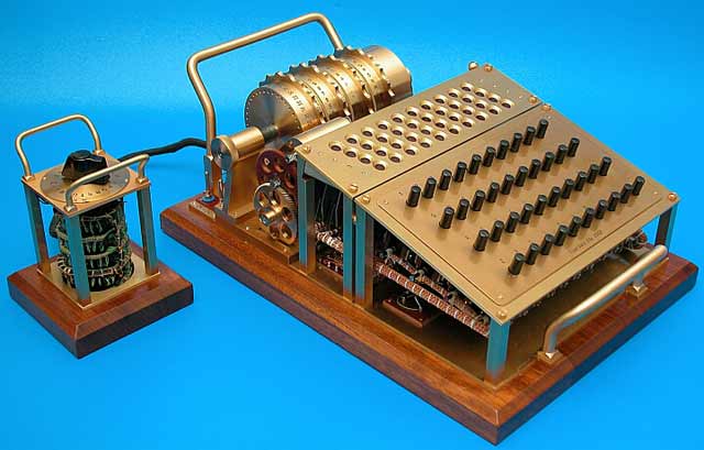
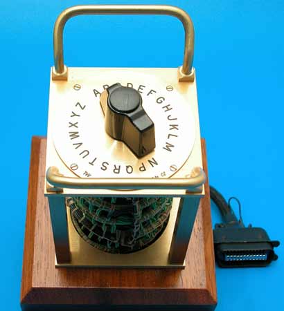
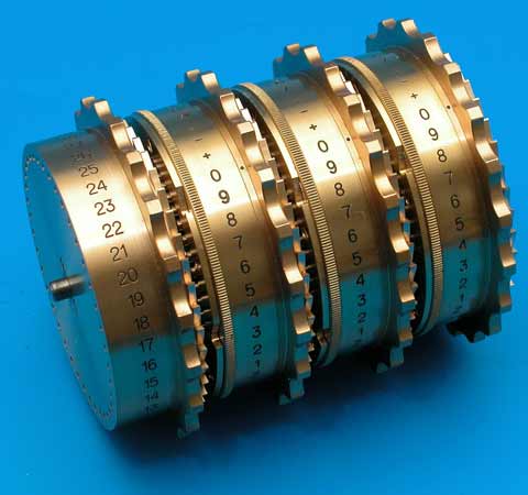
119 ABSOLUTELY INCREDIBLE ENHANCED ENIGMA-INSPIRED CIPHER
MACHINE MADE BY TATJA VAN VARK, EDE, THE NETHERLANDS:(35KB)Tatja has
always been interested in all kinds of mechanical and electronic devices. She
was particularly fascinated by the Enigma machine and wanted to own one but an
original was out of reach and she decided to build her own. After studying
a short description of the principles of the Enigma,
she decided to design and build an improved cipher machine and a printer
similar to the German Schreibmax printer which worked with the Enigma.
Tatja has no formal education in electronics or mechanics. As she puts it: "I
wanted to own a coding machine and now I do." Building it took about 8
months. No wonder when you see how many parts are inside, and everything had
to be home made. For example, each of the rotors has 509 individual parts.
She is particularly proud of the helical gearing in both the cipher machine
and the printer. Tatja makes everything herself including the varnish which
is made from all natural ingredients.
A nearby museum has asked her to restore their Enigma machine and to
give a lecture and demonstration of both machines. She is now working to
restore the museum's automatic telephone exchanges and carrier wave
equipment.
The machine now has the looks and uses many of the priciples of the original
Enigma but it has much stronger coding capabilities. She says:
"I will bet that nobody in the next hundred years will be able to decipher
the short message I created with my machine:
GUK59 XBOFJ
-AFF1 SGU65 0-KME YKCL7 76PRO LIKNY /WVSZ X-JYI OS6GN 9GLYL
CTOSE -UBO6 OFD7P I+M3J
Here is a collection of photographs of Tatja's fascinating cipher
machine and of some of the other amazing instruments that she has built
as well as a photograph of this extraordinary woman. Please visit
Tatja's website:
http://www.tatjavanvark.nl
for much more detailed descriptions of her work and more
photographs of her various projects.
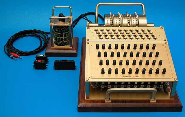
Another View of Tatja's Enigma-inspired Cipher
Machine:(33KB)
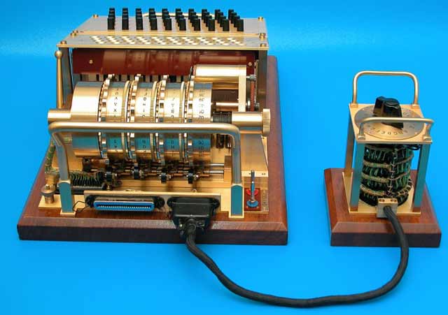
Another View of Tatja's Enigma-inspired Cipher
Machine:(32KB)
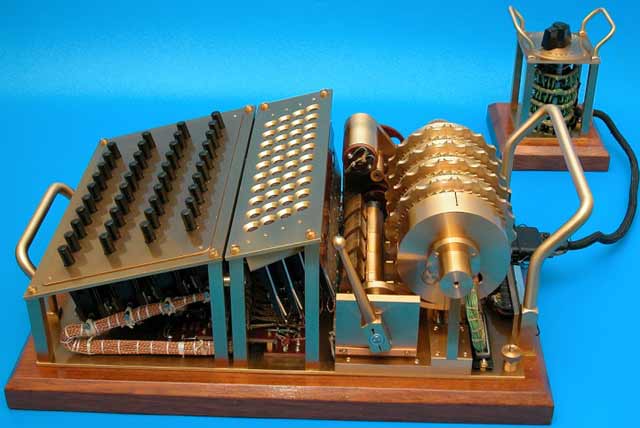
Another View of Tatja's Enigma-inspired Cipher
Machine:(33KB)
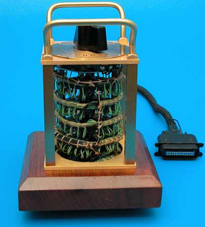
A View of the switch she designed to replace the
plugboard typically found on the German Enigma machines:(19KB)
Another View of the switch:(17KB)
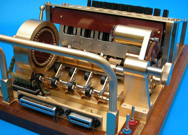
An internal View of Tatja's Enigma-inspired Cipher
Machine:(40KB)
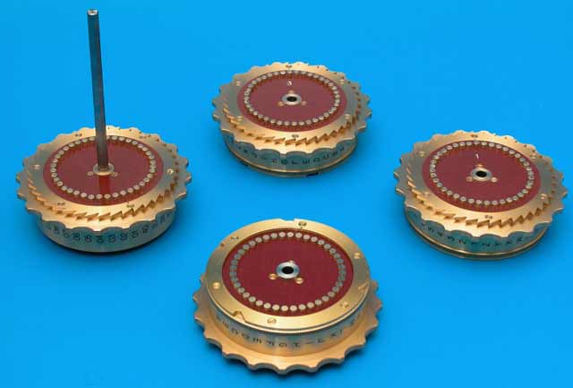
The four rotors of Tatja's Enigma-inspired Cipher
Machine:(21KB)
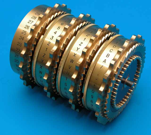
Another View of the rotors:(38KB)
Another View of the rotors:(23KB)
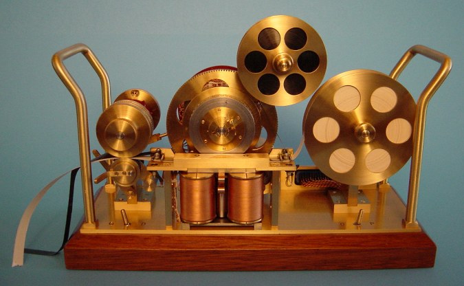
The magnificent printer which she made for her
Enigma-inspired Cipher Machine:(62KB)
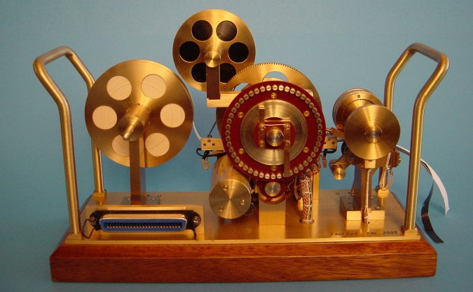
Another view of the printer for her
Enigma-inspired Cipher Machine:(59KB)
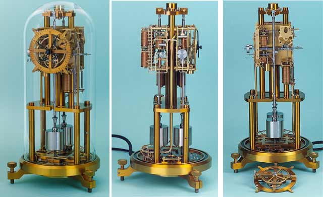
Tatja's FREE PENDULUM TIMEKEEPER:(34KB) This is a
miniature version of the Shortt Synchronome time standard. Taja began this
project in 1982 but after three months of work, a fundamental problem surfaced
and for the next 17 years she explored various solutions. She completed the
instrument just in time for the Milennium Celebration.
A photograph of Tatja van Vark:(14KB)
Here are some very interesting and informative INTERNET SITES AND REFERENCES DEVOTED TO THE ENIGMA:
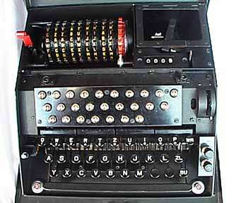
120 SWISS 'NEMA' VERSION OF THE GERMAN ENIGMA
MACHINE:(15KB)
The NEMA worked on the same principles as the Enigma. The 4 active rotors
each had an easily adjustable ring-setting wheel that could be changed as
though it was one of the rotor thumbwheels. All these thumbwheels gave the
erroneous impression that the NEMA had 10 rotors. The military or war version
was supplied with two additional rotors, 'E' and 'F' that were stored inside
the top cover. The NEMA was made by Zellweger A. G. in Uster.
An interesting feature of this machine is a remote light panel which
can be positioned in such a way that the person typing in the
coded letters can't see the message as it is decoded. This machine
is apparently also capable of feeding its output into a printer.
120a A view of the Swiss Enigma with case
closed:(14KB)
120b view of the inside of the cover showing the
power cord, remote light panel, and spare code wheels:(19KB)
The remote light panel could be used to prevent the keyboard
operator from seeing the decoded messages.(sold 02/14/1999)
120c A close-up view of the code wheels:(19KB)
120d Typing a letter causes another letter to light
up:(23KB)
120e Typing the same letter again causes a different
letter to light up:(22KB)
120f A close-up view of an illuminated
letter:(12KB)
120g A view of the Enigma with inside cover open and a
light bulb illuminated:(24KB)
120h A close-up view of the code wheels locked in
place:(20KB)
120i A close-up view of the code wheels in unlocked
position ready to be removed:(24KB)
120j The mechanism which causes the wheels to rotate
with every keypress:(25KB)
120k A close-up view of the stack of code wheels
after removal:(30KB)
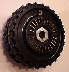
120l A close-up view of the code wheel labeled 'D'
showing the electrical contacts;(14KB)
121 ANOTHER NEMA CIPHER MACHINE:(21KB)
Here are some views of a second Swiss NEMA cipher machine often called
the Swiss Enigma:
121a A closer view of the NEMA with cover
closed:(25KB)
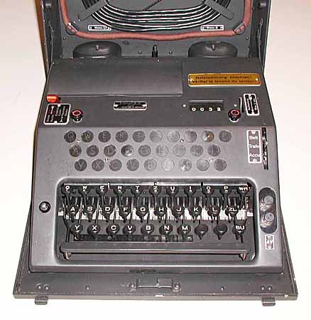
121b A closer view ofthe NEMA with cover
open:(28KB)
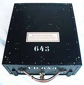
121c A view of the NEMA with case closed:(15KB)
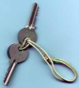
121d A view of the Keys for the case of the
NEMA:(15KB)
123 BETTER PHOTOGRAPHS OF ANOTHER NEMA CIPHER
MACHINE:(37KB)
This is another Swiss NEMA cipher machine which I have photographed
with a better digital camera. Please see item # 120 for a complete
description of the NEMA cipher machine.
123a A front view with the cover over
the code wheels open:(38KB)
123b
A front view with the cover over the entire mechanism and light bulbs
open:(41KB)
1223c
A close-up view of the code wheels in place in the machine:(53KB)
123d
A close-up view of the mechanism which rotates and reads the
code wheels:(50KB)
123e
A close-up view of the code wheels, spare wheels, and covers out of the
machine:(34KB)
123f
A close-up view of the code wheels and shaft out of the machine:(28KB)
123g
An overall view of the entire cipher machine with cover open:(20KB)
123h
A closer view of the inside of the cover showing all the power cables,
data cables, power adapters, and cleaning brush:(30KB)
123i
A closer view of the inside of the cover showing the spare code
wheels with their covers removed:(41KB)
123j
An overall view of the cipher machine with cover closed showing the
two original keys:(25KB)
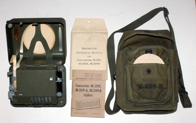
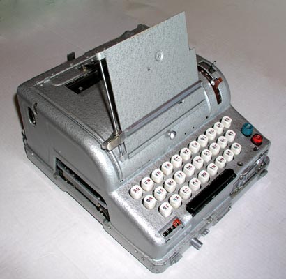
140 UNITED STATES M-209 WW-II CIPHER
MACHINE:(12KB)
More detailed photographs of the M-209, the entire M-209 field operation and
maintenance manual and an original 30-minute WW-2 M-209 training film complete
with big band musical background are included in The
Story of the ENIGMA CD described at the top of this museum page.
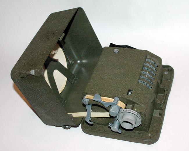
A closer view of the M-209. Note the paper tape printing mechanism on the left
side. The lowest knob can be set to "C" for "Cipher" the input or "D" for
"Decipher" the input.
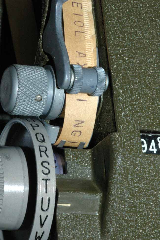
A much closer view of the paper tape printing mechanism. You can see some
enciphered letters that have been printed on the tape. Note also the
lettered wheel that is used to input letters into the cipher machine.
Turning the wheel so the desired letter ("u" in this case) is adjacent to the
white index mark and then turning the big black handle on the other side of
the machine operates the mechanism and prints the ciphertext on the
paper tape.
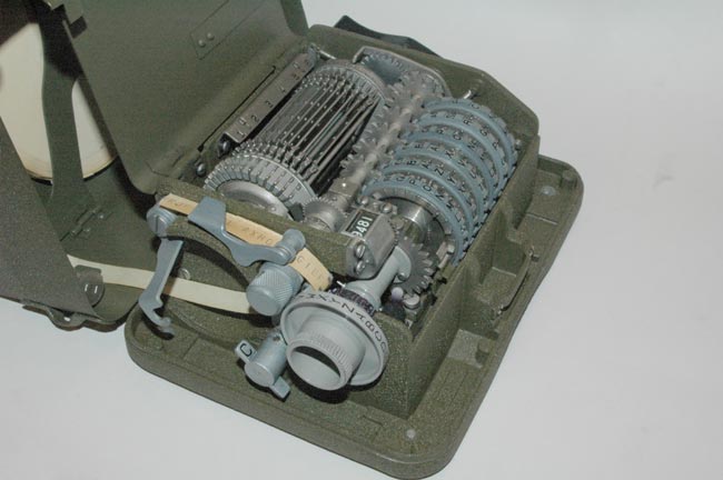
A view of the M-209 with the cover opened to allow access to the programming
mechanism. The "Cipher/Decipher" knob is set to "C", the "Cipher" mode,
which enciphers the plaintext input letters and prints the ciphertext on the
paper tape.
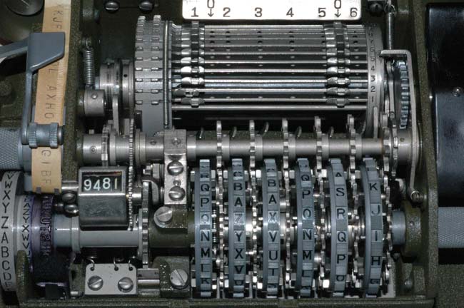
A closer view of the internal programming mechanism. The input wheel and
printer are on the left. The character counter is also on the left. The 6
code wheels are in front and the programming wheel is in the background.
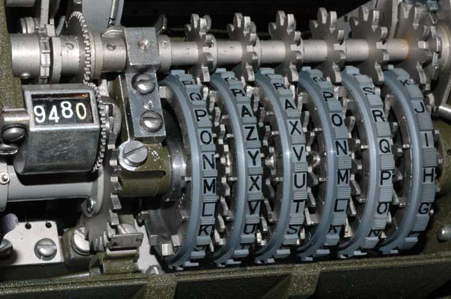
A closer view of the 6 code wheels. If you look closely, you can see the
individual pins that can be moved from side to side at each of the 26 letter
positions of each of the 6 wheels to control the rotation of each wheel.
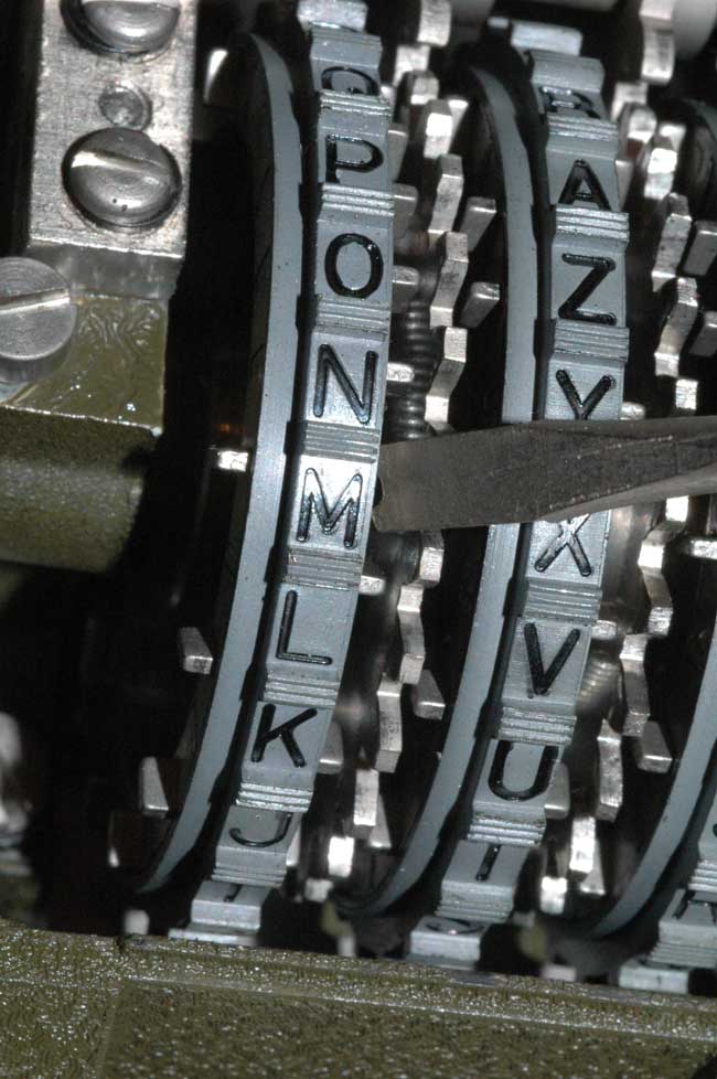
A closer view of the pins that determine the rotation of the leftmost
programming wheel. The pin adjacent to the letter "M" is being pushed to
the left position.
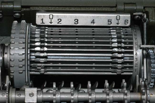
The pins on the left side of the programming matrix in the background have
been set to the "1" position. The pins on the right side have been set to
the "0" position.
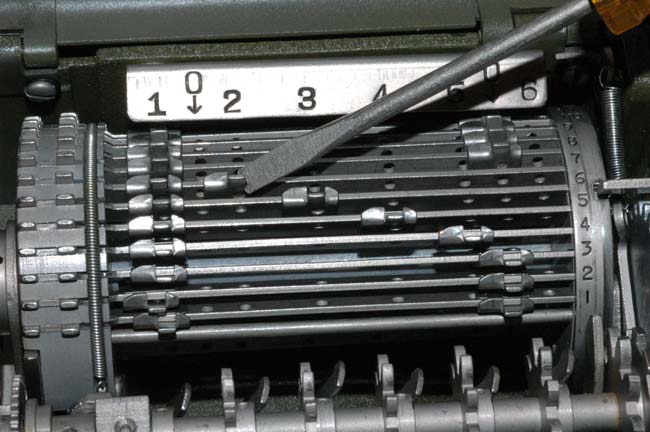
This picture shows how the individual pins are set using the specially notched
screw driver. If they are not set carefully so that they click into
position, the machine may jam.
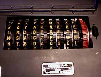
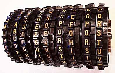
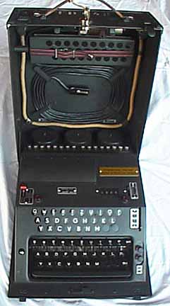
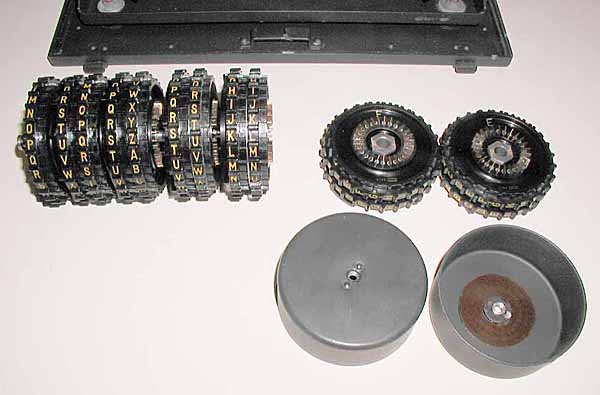
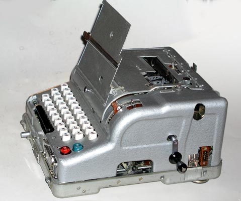
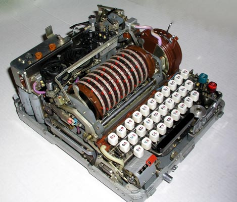
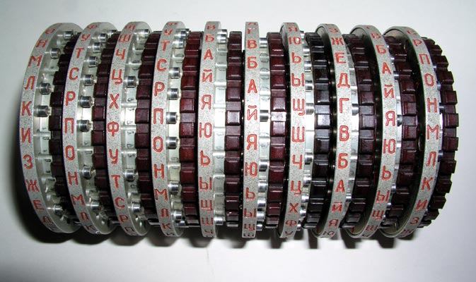
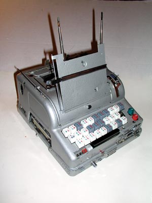
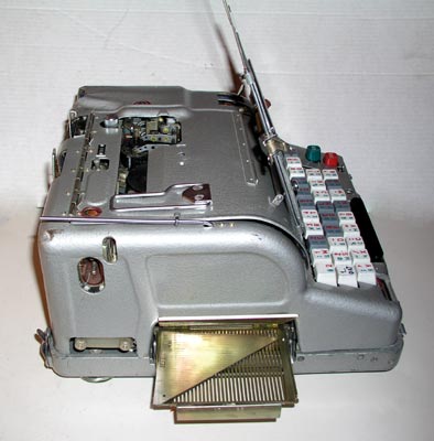
RUSSIAN COLD WAR ERA M-125 FIALKA CIPHER MACHINES:
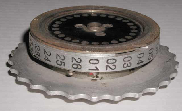
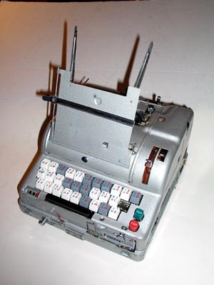
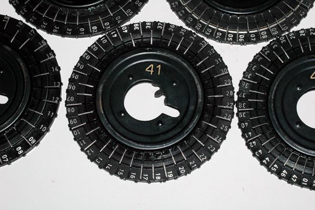
170 RUSSIAN COLD WAR ERA M-125 FIALKA CIPHER
MACHINE:
Very little information has previously been available about this interesting
machine. I have produced a set of hundreds of detailed photographs and descriptions of
my Fialkas and their disassembly as well as rotor wiring and rotation advance
data for the two different Fialka rotor sets. They may all be viewed in the
THE STORY OF THE ENIGMA CD.
If you have a fast internet connection, you can see much of this information
by selecting the LARGE scrollable picture-filled pages from the following
Fialkia Menu. The size of each page is given for each selection. If you have
a slow internet connection, you can read the following introduction and click
on the pictures and read the descriptions that follow the introduction.
INTRODUCTION TO THE RUSSIAN FIALKA:
GENERAL DESCRIPTION:
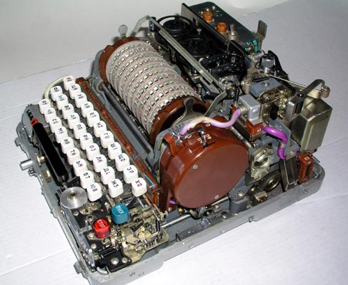
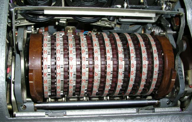
The Fialka is generally similar in design to the German Enigma cipher machine
but it has 10 rotors with 30 Russian characters/contacts instead of the 3 or 4
rotors with 26 letters/numbers/contacts in the German WW-2 Enigmas. The first
version of the Fialka, the M-100 was produced in the 1930s and it was followed
by the M-105 and then the M-125 models described here. The M-125 models
include the M-125-MN and the much more complicated M-125-3MN. (M-125-3MP3 and
M-125-3MP2 models have also been reported. They appear nearly identical
with the M-125-3MN but may have different keyboards.) The codename "FIALKA"
is the Russian word for "VIOLET".
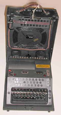
INPUT AND OUTPUT:
Instead of illuminating light bulbs to display the output characters resulting
from inputting characters into the keyboard, the Fialka prints the output
characters on paper tape and simultaneously punches holes in the tape in 5
level characters resembling those of a Baudot teletype machine tape. The
Fialka also includes a paper tape reader for use in rapidly inputting
characters that have been punched into a paper tape.
CARD READER:
The Fialka incorporates a card reader which allows punched paper cards to be
used to set internal coding parameters. These cards replaced the clumsy,
difficult-to-set, and therefore error-prone plugboards of the German
Enigmas.
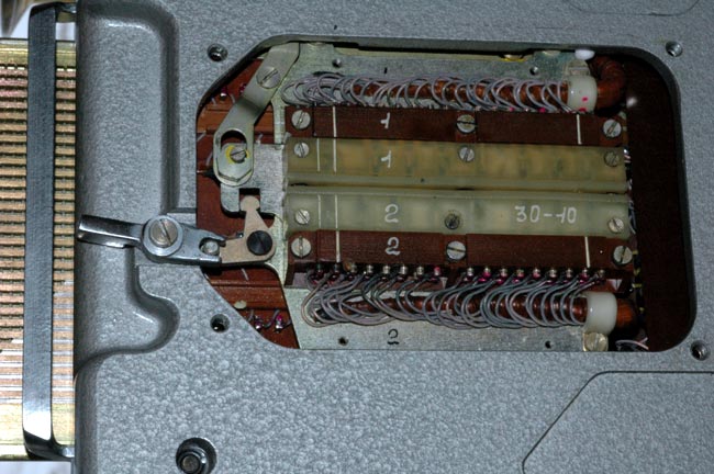
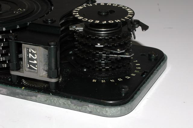
DIRECTION OF ROTOR ROTATION:
The Fialka rotates each of its 10 rotors in a direction that is opposite to
that of each neighboring rotor. Most other cipher machines have rotors that
all turn in the same direction. The pins that control the
rotation of individual rotors are described and the locations of all pins for
all rotors are given in tables in this rotor description link:
UNIQUE REFLECTORS:
The reflector at the left of the rotor stack is different from the reflector
in an Enigma and different in each Fialka model. Unlike an Enigma which has a
completely self-contained reflector, the reflector in the M-125-MN Fialka has
one bundle of wires extending down from it. The reflector in the M-125-3MN /
-3MP3 has three bundles of wires coming out of it.
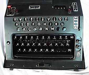
MULTI-LINGUAL OPERATION:
The M-125-3MN and M-125-3MP3 models differ from the M-125-MN models in that
they incorporate multi-lingual keyboards and some unique and complex switches
that allow the machine to function with several languages.
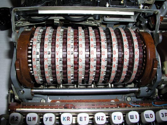
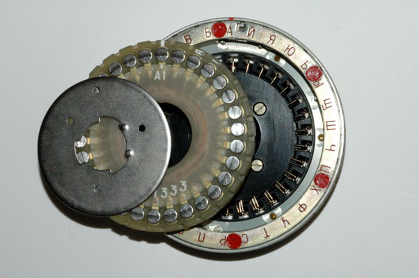
ROTORS:
There are two different sets of 10 rotors that can be inserted into either
machine. If present, the second set of rotors may be carried in a cylinder
inside the cover of the machines. One set is non-adjustable with fixed ring
settings and a fixed wiring maze. The other set is exceptionally cleverly
designed in that it allows for both the normal Enigma-like changes in ring
settings (the outer lettered ring may be rotated) coupled with the ability to
actually remove the internal wiring maze module from each rotor. Once the
wiring maze is removed, it may be reinserted into the rotor in any of the 30
possible positions and/or flipped upside down and inserted in any of the 30
positions to give a total of 60 unique wiring circuits. In addition, the
wiring maze module itself may be removed from the rotor and inserted into a
different rotor.
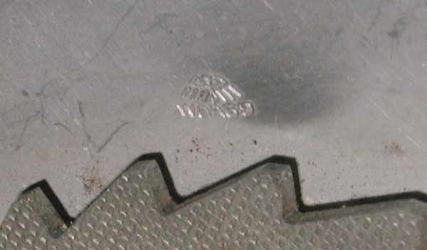
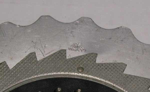
There are at least two series of rotors. Each series has unique wiring and
rotation blocking pin locations. Each series is documented in the links that
accompany this publication. One wiring and rotation option is found in the
series of rotors with the numerical prefix '3K'. At lease some of these
rotors are known to have come from Poland. A second wiring and rotation
option is found in the series of rotors with the numerical prefix '6K'. At
least some of these rotors are known to have come from the former
Czechoslovakia. It is possible, therefore, that the different series were
used in different countries and/or by different military entities. All rotor photographs and wiring data are given in this rotor
description link:
DESCRIPTIVE PHOTOGRAPHS:
The following photographs should help to clarify the comments and descriptions
above: Hundreds of additional Fialka photographs, descriptions and wiring and
rotation data tables are available in THE STORY OF THE
ENIGMA CD and some may be viewed in the links listed in the Fialka Menu at
the top of this section. Much higher resolution versions of all of these
Fialka photographs are available on a separate Fialka CD.
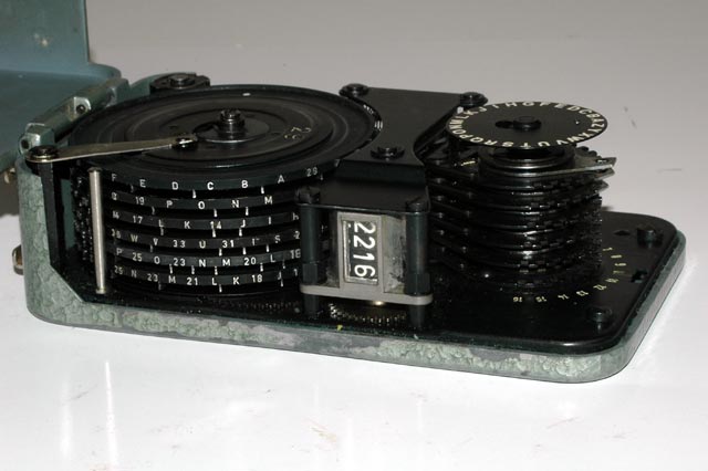
THE MODEL M-125-MN FIALKA:
(45 additional photographs and descriptions can be found in this link):
170s1h A left side view of the Model M-125-MN Fialka showing the slot for
inserting a punched paper programming card:
170s3d A right side view of the Model M-125-MN Fialka
showing the emergency hand crank and the a slot for activating a mechanical
switch under the rotors:
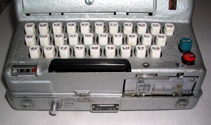
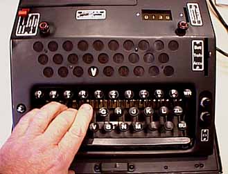
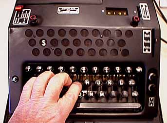
170s1i A closer view of the keyboard
showing the character counter and paper tape reader:
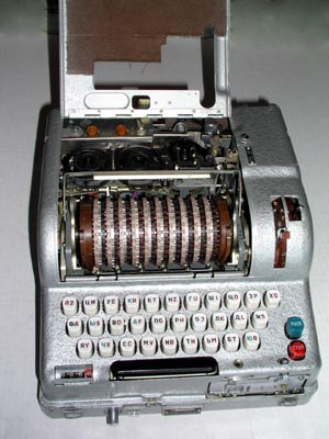
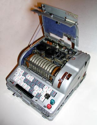
170s1k A view of the 10 rotors after
opening the cover. The paper tape printer and punch are also visible
behind the rotor stack.
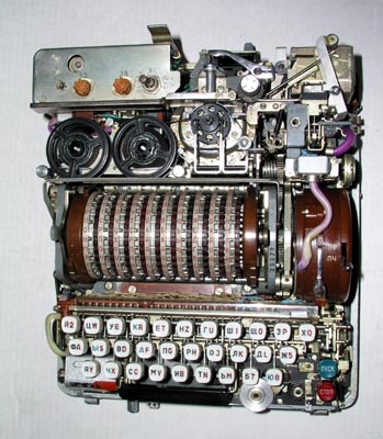
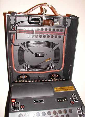
170s1n A top view of the Fialka after the
cover has been removed (3 screws). The paper tape printer and punch are
visible behind the rotor stack:
170s1o The left side of the Fialka with
the cover removed:
170s1p The right side of the Fialka with
the cover removed:
170s1t A view of the 10 rotors with the outer levers in
the released position. The brown reflector on the left and input wheel on
the right have been moved out and the index bar has been raised to facilitate
rotor removal:
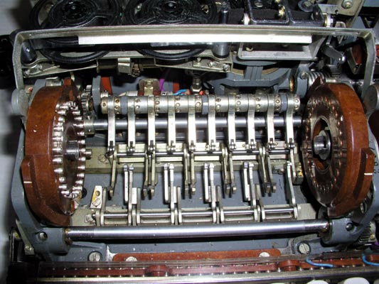
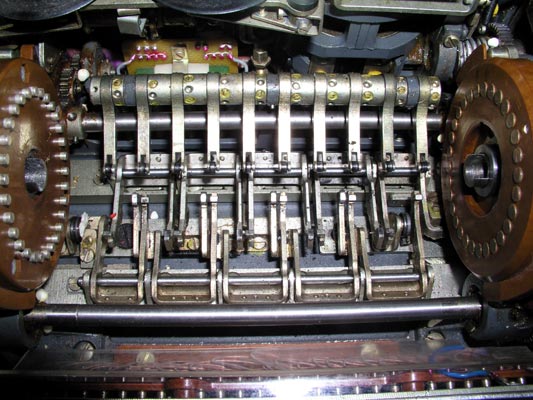
170s1u Removing the rotors reveals the
complex drive cog mechanism that causes each rotor to revolve in a different
direction from the adjacent rotor:
The lower horizontal bar activates cogs that pull forward on the bottoms of
rotors 2, 4, 6, 8 and 10 (counting from left to right) and rotate them so that
the tops of the rotors move AWAY from the keyboard.
The upper horizontal bar activates cogs that pull back on the bottoms of
rotors 1, 3, 5, 7 and 9 (counting from left to right) and rotate them so that
the tops of the rotors move TOWARD the keyboard.
A set of 10 spring-loaded arms with rollers holds the 10 rotors in their
detent positions.
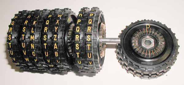
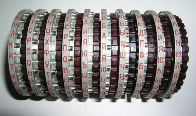
170s1v A view of the 10 rotor stack after
removal from the Fialka. The rotors may be removed from their shaft and
moved to different positions as shown in this photograph:

170s6e The 10 rotors have a fixed
internal wiring maze connecting the input contacts to the output contacts.
It may be uncovered as shown, but it is not designed to be modified:
The Model M-125-3MN / -3MP3 Fialka:
(42 additional photographs and descriptions can be found in this link):
(90 additional photographs of the disassembly of the Model M-125-3MN / -3MP3
Fialka can be found in this link):
This model is MUCH more complex than the M-125-MN model.
it has the following additional features:
1. A multilingual keyboard.
2. A mechanical switch along the right side of the keyboard
that modifies keyboard function.
3. A 3-position lever on the back of the Fialka that modifies paper tape
punch operation.
4. A large matrix switch that alters the wiring of the programming matrix and
therefore the effect of the programming cards.
5. A rotary switch located under the base of the Fialka.
6. A position on the switch located to the right of the input wheel that
stops rotation of the rotors and character counting as characters are typed
into the keyboard.
7. An extended copyholder.
171s1a The left side view of the M-125-3MN Fialka shows the copy holder with
its extensions, the character counter, the multilingual keyboard, and the slot
on the left side for the paper programming card.
171s1k The carrier for the paper programming card being pulled out of the left
side of the Fialka to allow insertion of the card.
u_171s5i The complicated multi-contact switch located under the punched paper
programming card that switches many of its contacts. This switch is not
found in the M-125-MN model.
171s1b The Right side of the Fialka showing the copy holder and input wheel
levers. The switches under the keyboard and rotors, and the hole for the hand
crank that allows manual operation of the Fialka are just barely visible.
u_171s1c The 10 rotors after the cover door is opened. The index bar has been
lowered in place in front of the rotors to allow accurate setting.
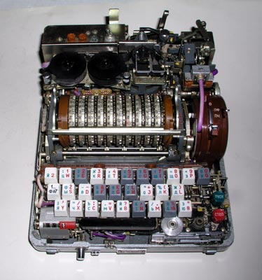
u_171s1w A top view of the Fialka with cover removed (3 screws).
The power switch and fuses are in the left rear. The paper tape printer
ribbon reels, the printer and the paper tape punch are behind the 10 rotors.
The brown reflector is on the left end of the rotor stack. The input wheel is
on the right end of the rotor stack. The keyboard and paper tape reader with
its manual paper tape feed wheel are in front.
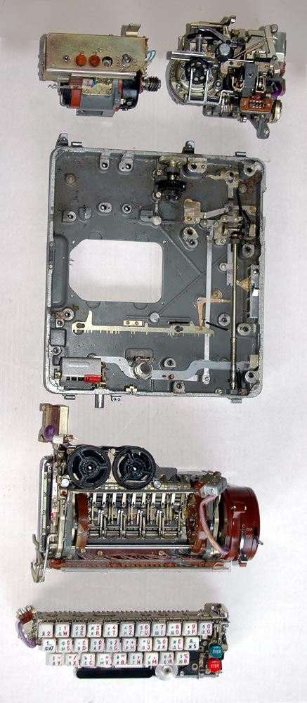
u_175s4w A top view of the Fialka showing all 5 of the modular components
after disassembly.
The Electric Motor is in the top left.
The Paper Tape Punch and Printer is in the top right.
The Base Plate is in the middle of the picture.
The Rotor Mechanism is below the base plate.
The Keyboard is below the rotor mechanism.
u_171s1m A closer view of the 10 rotors with the index bar raised to permit
removal of the rotor stack.
The two rounded levers that push the reflector on the left and the input wheel
on the right inward have been pulled forward so that the reflector and input
wheel may be pushed outwards to allow the rotor stack to be removed.
These rotors are the Non-Adjustable rotors. The multi-adjustable rotors
are described later under accessories and in the special detailed section on
rotors and rotor movement.
u_171s1y The drive mechanisms that produce the rotation of alternate
rotors.
The lower horizontal bar activates cogs that pull forward on the bottoms of
rotors 2, 4, 6, 8 and 10 (counting from left to right) and rotate them so that
the tops of the rotors move AWAY from the keyboard.
The upper horizontal bar activates cogs that pull back on the bottoms of
rotors 1, 3, 5, 7 and 9 (counting from left to right) and rotate them so that
the tops of the rotors move TOWARD the keyboard.
A set of 10 spring-loaded arms with rollers holds the 10 rotors in their
detent positions.
u_171s1n The 10 rotor stack of Non-adjustable rotors is shown here after
removal from the Fialka. The rotors may be removed from the shaft and
reinserted in any order:
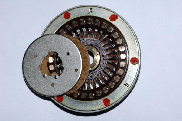
u_171s6e The internal hand-wired set of connections between the input contacts
and output contacts of this Non-Adjustable rotor is called a wiring maze.
It can be inspected or repaired by removing a metal disc as shown here. The
wiring of these non-adjustable rotors is not designed to be changed.
u_170s6p The Multi-Adjustable Rotors can have their modular wiring maze
removed and reinserted in 60 different ways. Their outer ring setting can
also be changed in 30 ways. Details and more pictures are in the links above.
The Multi-Adjustable Modular Wiring Maze Rotors, other accessories, and
metal cover:
(22 additional rotor photographs, descriptions, and data tables
can be found in this link):
(17 additional photographs and descriptions of the accessories
can be found in this link):
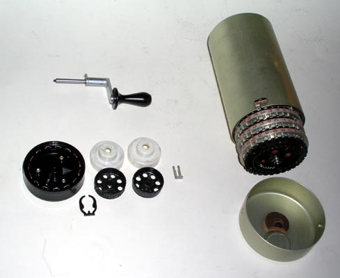
u_170s7u The Cover of the Fialka may contain a number of accessories
including a set of complex multi-adjustable modular wiring maze rotors,
additional print wheels, a rotor spacer, and a hand crank.
THE 24 VOLT POWER SUPPLY:
(8 additional photographs and descriptions can be found in this link):
u_170s8a The 24 Volt DC Power Supply.
ADDITIONAL FIALKA PHOTOGRAPHS AND DATA:
Hundreds of additional photographs, wiring and rotation data tables, and
descriptions are available in the ENIGMA CD and the
links in the Fialka Menu above and much higher resolution versions are
available on a special Fialka Research CD.
190 U.S.ARMY M-108 POCKET-SIZED BURST ENCODER / KEYER:
(25KB)
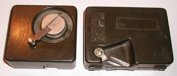
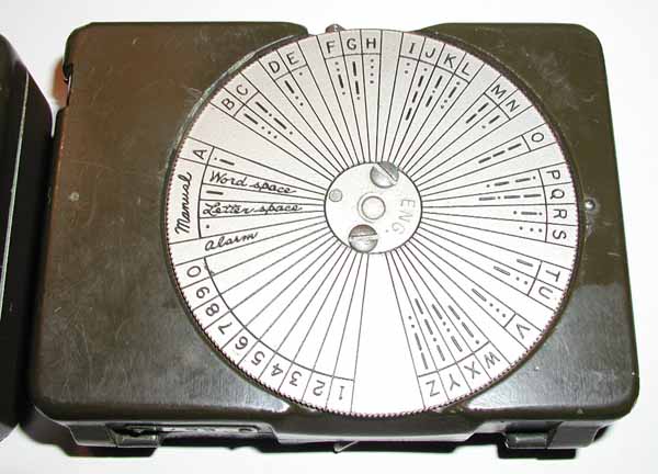
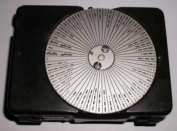
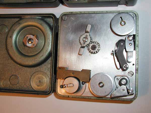
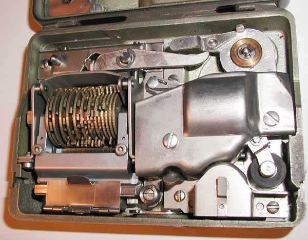
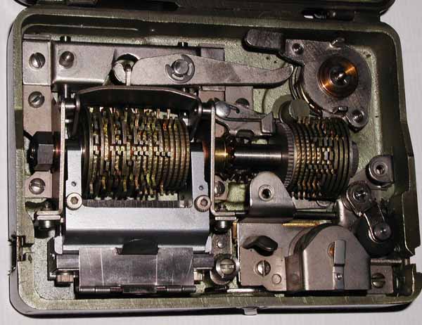
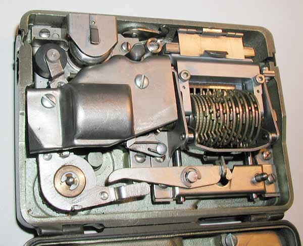
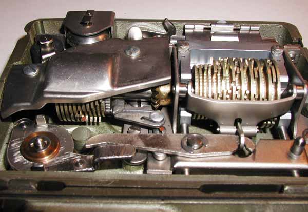
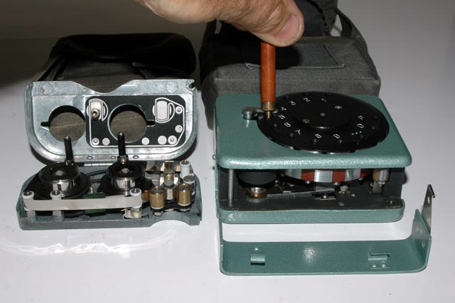
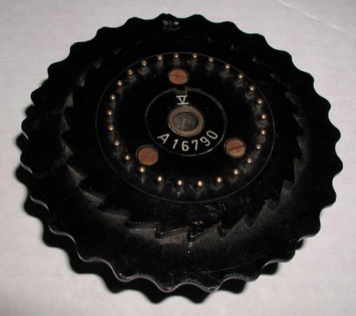
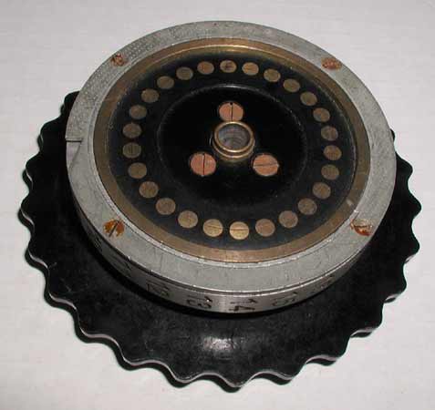
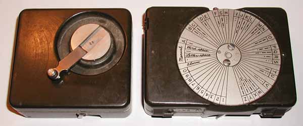
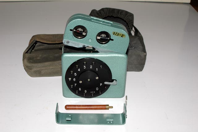
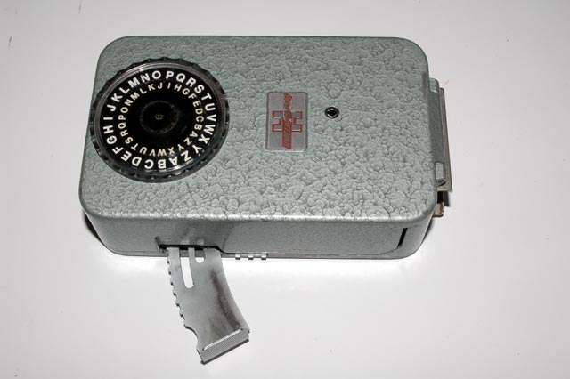
192f RUSSIAN NON-ELECTRONIC SPY POCKET BURST ENCODER:
(25KB)
The coding unit (with the dial) writes the magnetic pulses onto the tape by
direct magnetic induction without the use of any electronic circuitry. Each
dialed-in character rotates a series of permanent magnets past the tape. This
writes the pulses onto the tape and at the end of the dial's rotation, it
advances the tape. This makes the pocket encoder independent of any power
sources and completely portable.
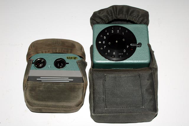
192a A view of the pocket encoder magnetic tape cartridge
and programming unit with their protective canvas carrying cases:
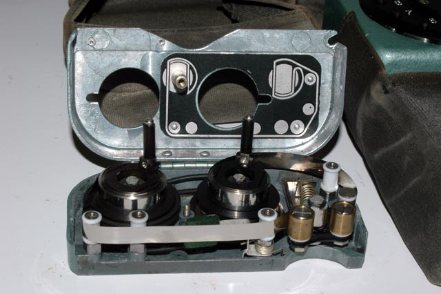
192c A closer view of the pocket encoder magnetic tape
cartridge which has been opened to show the internal tape transport mechanism:
192g A view of the pocket encoder magnetic tape
cartridge being inserted into the top of the programming unit:
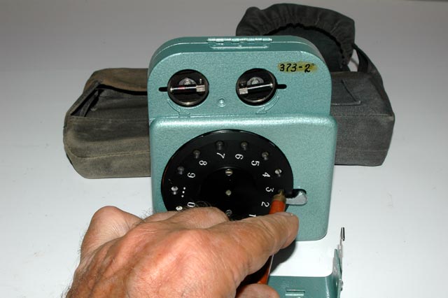
192i A view of the pocket encoder programming unit being
operated with the stylus. The magnetic tape cartridge is seen on top of the
programming unit:
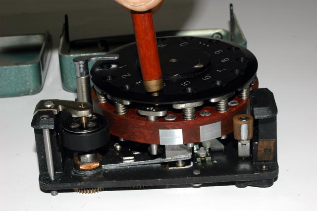
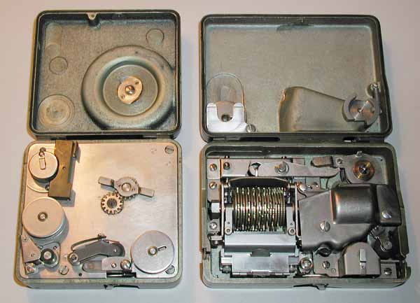
192o A view of the internal mechanism of the pocket
encoder programming unit being ooperated with the stylus. The permanent
magnets that pass by the magnetic tape and record the pulses on the tape can
be seen embedded in the brown plastic wheel:
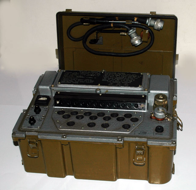
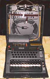
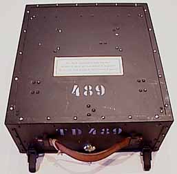
194c RUSSIAN ELECTRONIC BURST ENCODER Model R-014D:
(25KB)
This is a very complex and interesting burst encoder set which operates on
internal batteries and can input, store and send encoded messages at a very
high speed producing a burst of encoded data that keys a radio transmitter and
broadcasts a very short transmission containing the entire coded message.
These extremely short and fast messages are difficult for an enemy to receive
since they are only on the air for a very short time. The short duration of
the message burst also makes it difficult for the enemy to use direction
finding radios to pinpoint the location of the transmitter. The unit was used
with Russian Radio Station R-142. It was part of the "Automatic System for
Field Command" for sending secret information at high speeds with a maximum of
150 Baud. Disassembly of the device reveals a rather unique set of printed
circuit boards that are hinged at the back and open like a book for
servicing.
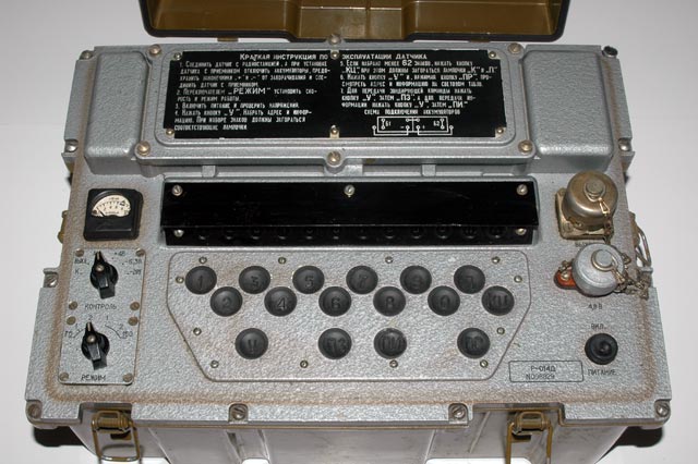
194b A closer view of the Russian encoder showing the
keyboard, display lamps, and controls:
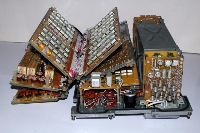
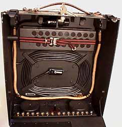
194n A view of the many printed circuit boards being
folded open like a book for inspection and servicing (The battery box is
seen on the right.):
194d A view of the unusual hinge and connector assembly
that allows the printed circuit boards to be folded open like a book for
inspection and servicing:
194n A view of the printed circuit boards
folded open like a book for inspection and servicing:
800 HAGELIN MECHANICAL POCKET CIPHER MACHINE:
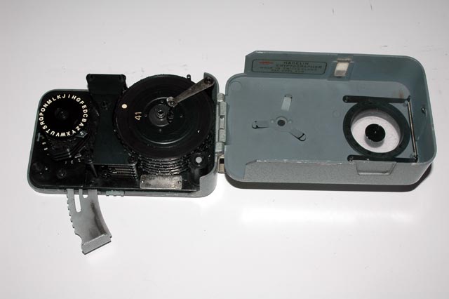
800a The HAGELIN Cipher Machine with its cover hinged
open to reveal the inner mechanism:
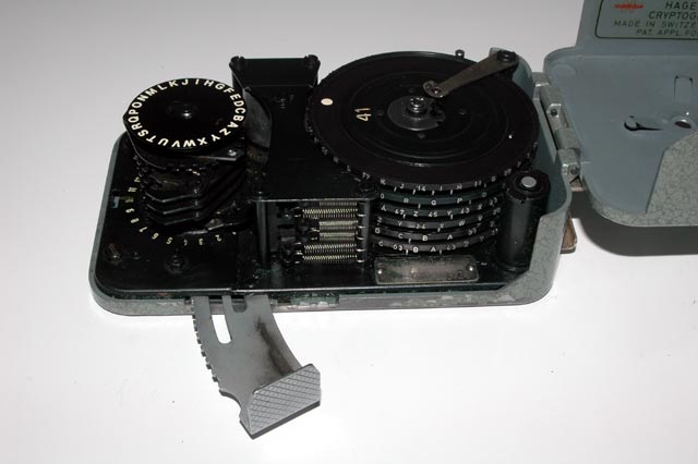
800b A closer view of the mechanism of the HAGELIN
Cipher Machine:
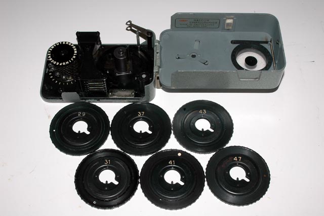
800c The HAGELIN Cipher Machine with the 6 rotors
removed to show the top side of each rotor:
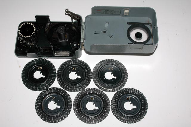
800d The HAGELIN Cipher Machine with the 6 rotors
removed to show the bottom side of each rotor and their internally adjustable
pins:
800e A closer view of several rotors showing
their internally adjustable pins:
800f A closer view of the mechanism of the HAGELIN
Cipher Machine showing the rotors and the character counter:
800g A closer view of the mechanism of the HAGELIN
Cipher Machine showing actuating mechanism:
* * THE STORY OF THE ENIGMA CD: History, Technology, and
Deciphering (NEW 4th Edition) (Details, Table of Contents & Ordering
Information)
This newly expanded CD is a complete cipher machine library. It has twice the
material in the 3rd edition. It tells the complete story of the ENIGMA !
Thousands of pictures, books, Enigma simulator programs, construction
projects, other cipher machines, realistic videos... and much more. $15. ** (Updates & Corrections)
* * NEW BOOK: INSIDE ENIGMA: Inside the German ENIGMA
and other Historic Cipher Machines
(Details, Table of Contents & Ordering Information)
This new book contains 208 pages and over 500 pictures that exlain the
history and workings of the ENGIMA and other cipher machines including the
Russian Fialka. $20. ** (Updates &
Corrections)
NOTE: WE ARE AM ALWAYS LOOKING TO BUY, TRADE, OR PHOTOGRAPH VERY UNUSUAL ENIGMA-RELATED ITEMS.
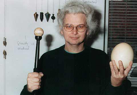
Thomas B. Perera Ph. D.
Professor Emeritus: Montclair State University
Curator: EnigmaMuseum.com
COPYRIGHT NOTICE: (Copyright (c) 2013, 2022: Prof. Tom Perera Ph. D.)
Although all the pictures and text are copyrighted, you may use any of them
for your own personal applications including public lectures and
demonstrations, publications and websites as long as you mention the
www.EnigmaMuseum.com or w1tp.com/enigma Museum. If you plan to offer them for sale to the public
in any form, you must email me for permission which I will generally grant as
long as you mention my museums: http://EnigmaMuseum.com or http://w1tp.com/enigma. My email address is
given at the bottom of this page. Some of the material may require contacting
other copyright owners for commercial use and I will inform you by email.
Please also see the disclaimer of warranty.